1. Introduction
The Generic FT245 USB Module is a communication development board designed to facilitate USB to Parallel FIFO (First-In, First-Out) data transfer. This module utilizes the FT245R or FT245RL integrated circuit, providing a simple and efficient way to interface parallel data buses with a USB host. It is ideal for applications requiring high-speed data transfer between a computer and various peripheral devices or microcontrollers.
Key features include USB connectivity and a parallel FIFO interface, making it suitable for a wide range of electronic projects and industrial applications.
2. Product Overview
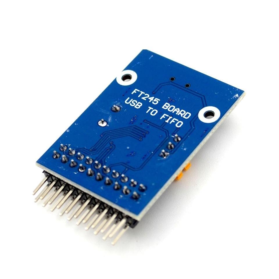
Figure 1: Top View of the FT245 USB Module. This image displays the component side of the module, featuring the mini-USB connector on the left, the main FT245R/RL chip, a crystal oscillator for timing, and various passive components. The power (PWR) LED is visible, along with a jumper for selecting between 3.3V and 5V VCCIO. The pin headers for the parallel FIFO interface and control signals are located on the right side, clearly labeled with functions such as RD#, WR#, RXF#, TXE#, RST#, D0-D7, and GND.
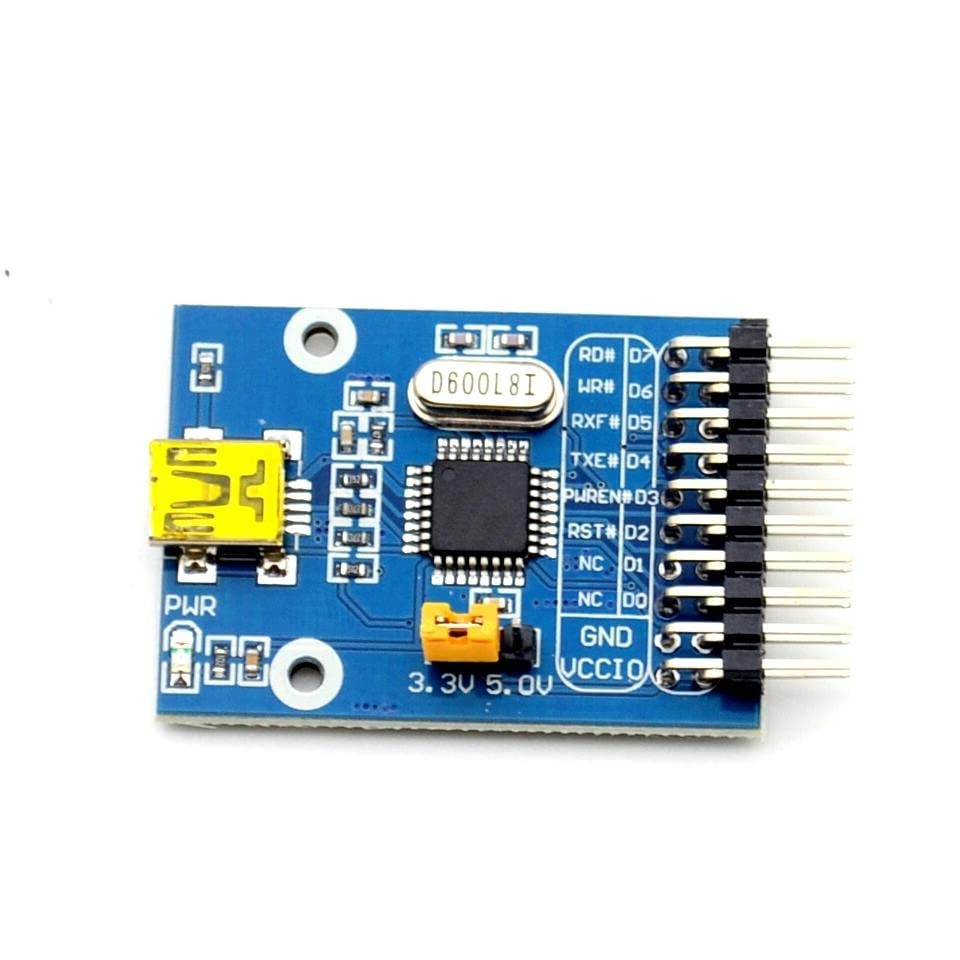
Figure 2: Bottom View of the FT245 USB Module. This image shows the underside of the circuit board. The primary feature visible is the silkscreen text 'FT245 BOARD USB TO FIFO', confirming the module's identity and function. The solder points for the pin headers are also visible, along with the copper traces connecting various components on the board.
3. Setup Instructions
3.1 System Requirements
- Operating System: Windows, Linux, macOS
- Compatible Devices: Microcontroller, Personal Computer
- Available USB port
3.2 Package Contents
- FT245 USB FIFO Board (mini)
- Jumper (for VCCIO selection)
3.3 Driver Installation
Before connecting the FT245 USB Module to your computer, it is recommended to install the necessary drivers. FTDI (Future Technology Devices International) provides Virtual COM Port (VCP) drivers and D2XX Direct drivers for various operating systems. These drivers can typically be downloaded from the official FTDI website. Follow the instructions provided by FTDI for proper driver installation.
3.4 Hardware Connection
- VCCIO Selection: Locate the VCCIO jumper on the module (refer to Figure 1). Set the jumper to either 3.3V or 5V, depending on the voltage requirements of your connected microcontroller or peripheral device. Ensure this matches the logic level of your external circuit.
- USB Connection: Connect the mini-USB port on the FT245 module to an available USB port on your computer using a standard mini-USB cable (not included). The power LED on the module should illuminate.
- Parallel FIFO Connection: Connect the parallel data bus (D0-D7) and control signals (RD#, WR#, RXF#, TXE#, RST#, GND) from the module to your microcontroller or target device. Ensure correct pin mapping and secure connections.
4. Operating the FT245 USB Module
4.1 Basic Operation
The FT245 USB Module acts as a bridge, converting data between the USB interface of your computer and a parallel FIFO interface. Data sent from the computer via USB is buffered in the module's internal FIFO and can be read by a parallel device. Conversely, data written to the module's parallel FIFO by an external device is buffered and sent to the computer via USB.
4.2 Data Transfer Modes
The module operates in a parallel FIFO mode. Data is written to or read from the 8-bit data bus (D0-D7) using control signals:
- RD# (Read Strobe): Active low signal used by the external device to read data from the FT245's FIFO.
- WR# (Write Strobe): Active low signal used by the external device to write data into the FT245's FIFO.
- RXF# (Receive FIFO Full/Empty): Active low output indicating the receive FIFO status. Typically low when data is available to be read by the external device.
- TXE# (Transmit FIFO Empty/Full): Active low output indicating the transmit FIFO status. Typically low when the external device can write data into the FIFO.
- RST# (Reset): Active low input to reset the module.
Refer to the FTDI FT245R/FT245RL datasheet for detailed timing diagrams and operational specifics.
5. Maintenance
To ensure the longevity and reliable operation of your FT245 USB Module, follow these maintenance guidelines:
- Handling: Handle the module with care, avoiding excessive force or bending. Electronic components are sensitive to physical stress.
- Environment: Store and operate the module in a dry, dust-free environment. Avoid exposure to extreme temperatures, humidity, or corrosive substances.
- Static Electricity: Always take precautions against electrostatic discharge (ESD) when handling the module. Use an anti-static wrist strap and work on an ESD-safe surface.
- Cleaning: If cleaning is necessary, gently wipe the board with a soft, dry, lint-free cloth. Do not use liquid cleaners or solvents. Ensure the module is powered off and disconnected before cleaning.
6. Troubleshooting
6.1 Common Issues and Solutions
- Issue: Device not recognized by the computer.
Solution:
a. Ensure the USB cable is securely connected to both the module and the computer.
b. Verify that the correct FTDI drivers are installed on your operating system. Reinstall drivers if necessary.
c. Try connecting the module to a different USB port on your computer. - Issue: Data transfer errors or no data flow.
Solution:
a. Check all parallel FIFO connections (D0-D7, RD#, WR#, RXF#, TXE#, RST#, GND) for correct wiring and secure contact.
b. Ensure the VCCIO jumper is set to the correct voltage (3.3V or 5V) matching your external device's logic levels.
c. Verify your software application or microcontroller firmware is correctly configured to communicate with the FT245 module's FIFO interface. - Issue: Power LED is not illuminated.
Solution:
a. Confirm the USB cable is properly connected and providing power.
b. Try a different USB cable or USB port.
c. Ensure your computer's USB port is functioning correctly and supplying power.
7. Technical Specifications
| Feature | Specification |
|---|---|
| Brand | Generic |
| Model Number | JXLiazcd_10969 |
| Connectivity Technology | USB |
| Operating System Compatibility | Windows, Linux, macOS |
| Compatible Devices | Microcontroller, Personal Computer |
| Included Components | FT245 USB FIFO Board (mini), Jumper |
| Total USB Ports | 1 (Mini-USB) |
| Processor Count | 1 (FT245R/RL) |
| Date First Available | Feb. 21 2023 |
8. Warranty and Support
For specific warranty information regarding your FT245 USB Module, please refer to the terms and conditions provided by your retailer or the manufacturer at the time of purchase. Warranty coverage typically addresses manufacturing defects.
If you encounter issues that cannot be resolved using the troubleshooting guide, or require further technical assistance, please contact the seller or the manufacturer directly. Provide your product model number (JXLiazcd_10969) and a detailed description of the problem to facilitate support.