Keenso Keensoe49hdtvkab
DC Motor Controller User Manual
Model: Keensoe49hdtvkab
Brand: Keenso
1. Introduction
This manual provides detailed instructions for the installation, operation, and maintenance of the Keenso DC Motor Controller. Designed for electric bicycles, this controller supports both 36V and 48V systems with a maximum current of 17A, suitable for 250-350W motors. Please read this manual thoroughly before use to ensure proper function and safety.
2. Safety Information
- Always disconnect power before installation or maintenance.
- Ensure all connections are secure and correct to prevent short circuits or damage.
- Do not expose the controller to excessive moisture or extreme temperatures.
- Consult a qualified technician if you are unsure about any installation steps.
- This device is intended for use with compatible electric bicycle motors and batteries only.
3. Product Overview
The Keenso DC Motor Controller is a compact and robust unit designed to manage power delivery to your electric bicycle motor. Its aluminum alloy shell provides excellent heat dissipation and durability.

Figure 3.1: Front view of the Keenso DC Motor Controller, showing the main unit and various colored wire harnesses extending from one end.
3.1 Key Features
- Compact Size: Easy to install, occupies minimal space.
- Universal Voltage: Compatible with 36V and 48V systems.
- High Current Capacity: Maximum current of 17A, suitable for 250-350W motors.
- Pre-wired Harness: Equipped with standard wires and interfaces for stable and reliable connections.
- Efficient Heat Dissipation: Grooved aluminum alloy shell prevents thermal overload.
- Durable Construction: Lightweight and resistant aluminum alloy material.
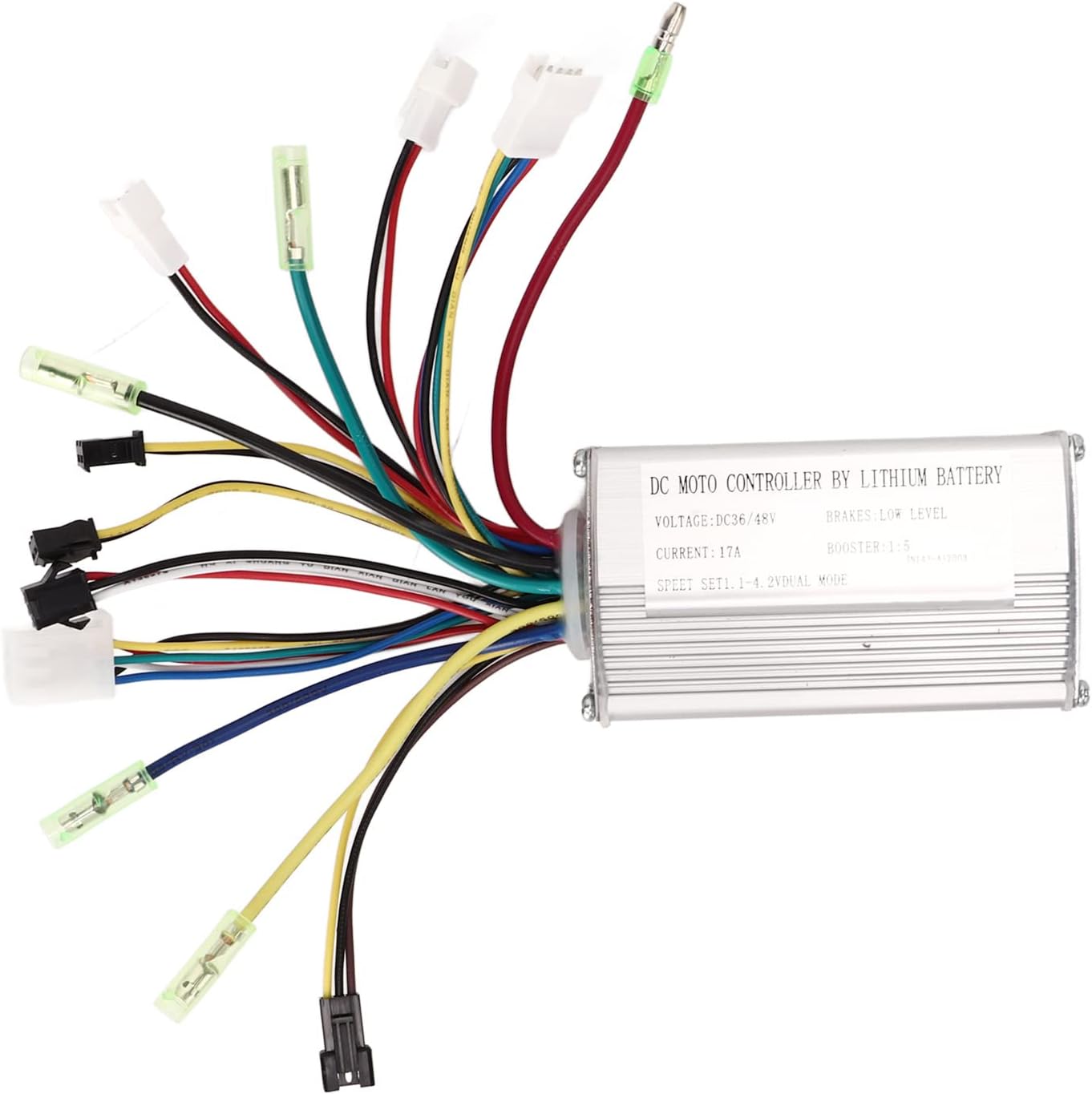
Figure 3.2: The Keenso DC Motor Controller with an overlay listing its key features, including 36V/48V compatibility, 250-350W motor applicability, groove design for heat dissipation, aluminum alloy shell, and standard wiring.
4. Specifications
| Feature | Value |
|---|---|
| Rated Voltage | 36V / 48V (Universal) |
| Maximum Current | 17A |
| Applicable Motor Power | 250W - 350W |
| Shell Material | Aluminum Alloy |
| Item Weight | 8.8 ounces (approx. 250g) |
| Package Dimensions | 5.31 x 3.94 x 3.23 inches |
| Model Number | Keensoe49hdtvkab |
5. Setup and Installation
Before beginning installation, ensure your electric bicycle's power is completely off and the battery is disconnected. Refer to the wiring diagram below for correct connections.
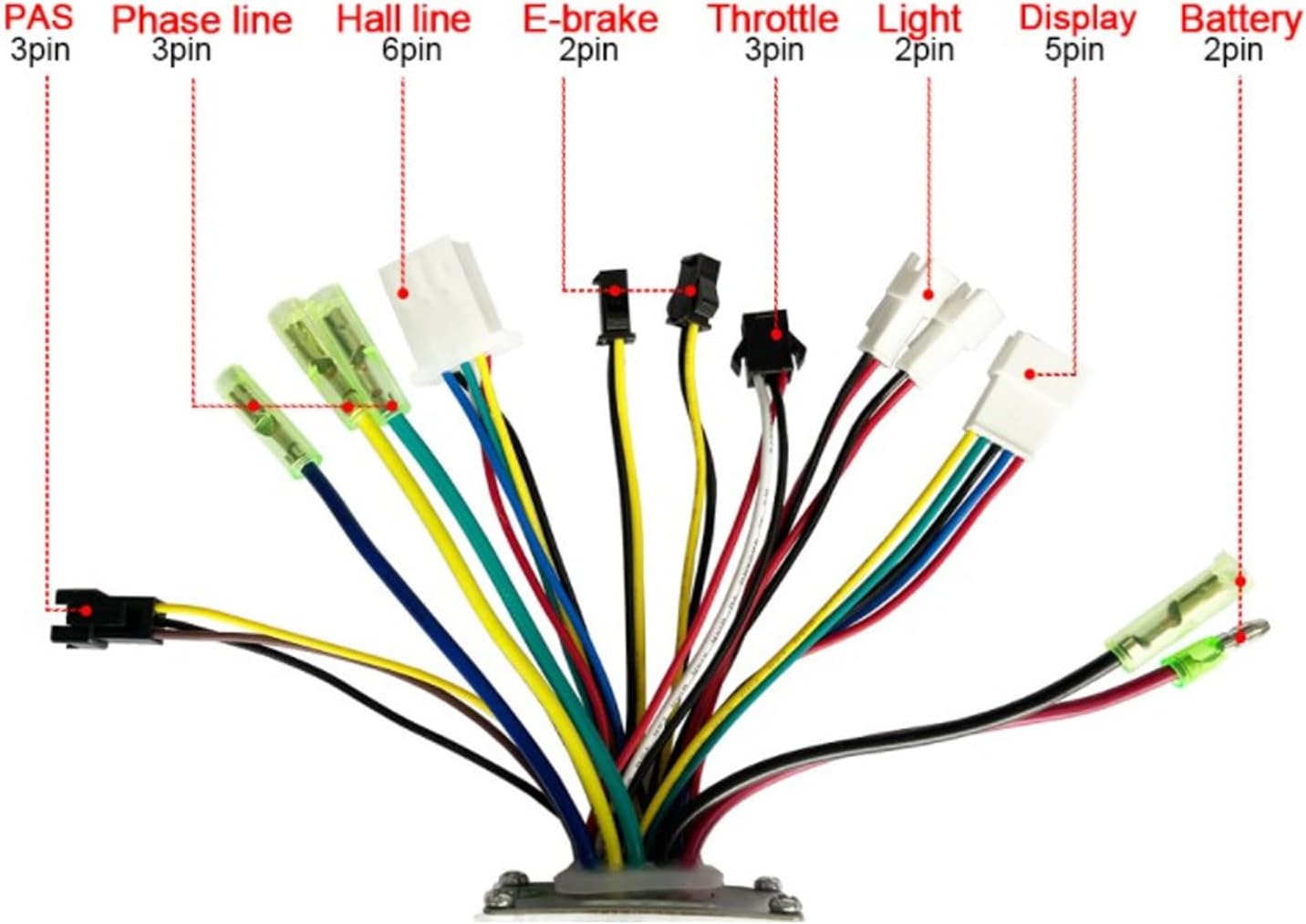
Figure 5.1: Detailed wiring diagram showing labeled connectors for PAS, Phase line, Hall line, E-brake, Throttle, Light, Display, and Battery connections.
5.1 Wiring Connections
- Battery Connection: Connect the main power wires (usually thicker red and black) from the controller to your 36V or 48V lithium battery. Ensure polarity is correct (red to positive, black to negative).
- Motor Phase Lines: Connect the three phase wires (typically green, yellow, blue) from the controller to the corresponding phase wires of your motor.
- Hall Sensor Wires: Connect the Hall sensor wires (usually five thin wires) from the controller to the motor's Hall sensor connector.
- Throttle: Connect the throttle connector to your e-bike's throttle assembly.
- E-Brake: Connect the E-brake connectors to your brake levers, if applicable. These typically cut motor power when brakes are applied.
- PAS (Pedal Assist System): Connect the PAS sensor to the controller's PAS input for pedal-assisted riding.
- Display/Light (Optional): Connect your display unit and/or lights to the designated connectors if your system supports them.
- Self-Learning Wires (if present): Some controllers have self-learning wires (often two white wires). Connect them briefly to allow the controller to learn motor parameters, then disconnect. Refer to specific motor/display instructions if needed.
After all connections are made, secure the controller in a safe, dry location on your bicycle, ensuring adequate airflow for heat dissipation.
6. Operating Instructions
- Power On: Once all connections are secure, connect your battery and turn on the main power switch of your e-bike (if equipped).
- Throttle Operation: Gently twist the throttle to engage the motor. The motor speed will increase with the throttle input.
- Pedal Assist (PAS): If a PAS sensor is connected, the motor will provide assistance when you pedal, based on the selected assist level (if using a display).
- Braking: Applying the brakes (especially those with E-brake cut-off sensors) will immediately cut power to the motor.
- Power Off: Always turn off the e-bike's main power switch and disconnect the battery when not in use or before performing any maintenance.
7. Maintenance
- Regular Inspection: Periodically check all wire connections for looseness or damage.
- Cleaning: Keep the controller clean and free from dust, dirt, and moisture. Use a dry, soft cloth for cleaning. Do not use harsh chemicals or abrasive materials.
- Heat Dissipation: Ensure the controller's fins are not obstructed to allow for proper heat dissipation.
- Storage: When storing the e-bike for extended periods, ensure the controller is kept in a dry, cool environment.
8. Troubleshooting
| Problem | Possible Cause | Solution |
|---|---|---|
| Motor not working | Loose battery connection; Faulty throttle; Motor or Hall sensor issue; Controller malfunction. | Check battery connections and charge level. Inspect throttle wiring. Verify motor and Hall sensor connections. If issues persist, consult a technician. |
| Intermittent power | Loose wire connections; Overheating controller; Low battery voltage. | Secure all connections. Allow controller to cool down. Charge battery fully. |
| Motor runs but with reduced power | Low battery charge; Incorrect voltage setting (if adjustable); Motor issue. | Ensure battery is fully charged. Verify controller is set to correct voltage (36V/48V). Check motor for damage. |
| Controller gets excessively hot | Overload (motor too powerful for controller); Insufficient ventilation; Short circuit. | Ensure motor power is within controller's specifications (250-350W). Improve airflow around controller. Check for short circuits in wiring. |
For problems not listed here or if solutions do not resolve the issue, please contact customer support.
9. Warranty and Support
Keenso products are manufactured to high quality standards. For information regarding warranty coverage, please refer to the purchase documentation or contact your retailer. For technical support or inquiries, please visit the official Keenso store on Amazon or contact their customer service directly.
Ask a question about this manual
Ask about setup, troubleshooting, compatibility, parts, safety, or missing instructions. Manuals+ will review the question and use this page’s manual context to help answer it.