1. Introduction
This manual provides detailed instructions for the safe and effective operation of the Eujgoov AUA280U Optical Time Domain Reflectometer (OTDR). The AUA280U is a multi-functional fiber optic cable tester designed for evaluating FTTx and access network construction and maintenance. It integrates OTDR, Visual Fault Locator (VFL), Optical Power Meter (OPM), and Optical Light Source (OLS functionalities.
2. Product Overview
The Eujgoov AUA280U features a compact design with a 3.97-inch IPS touch screen for intuitive operation. Key components and interfaces are illustrated below.
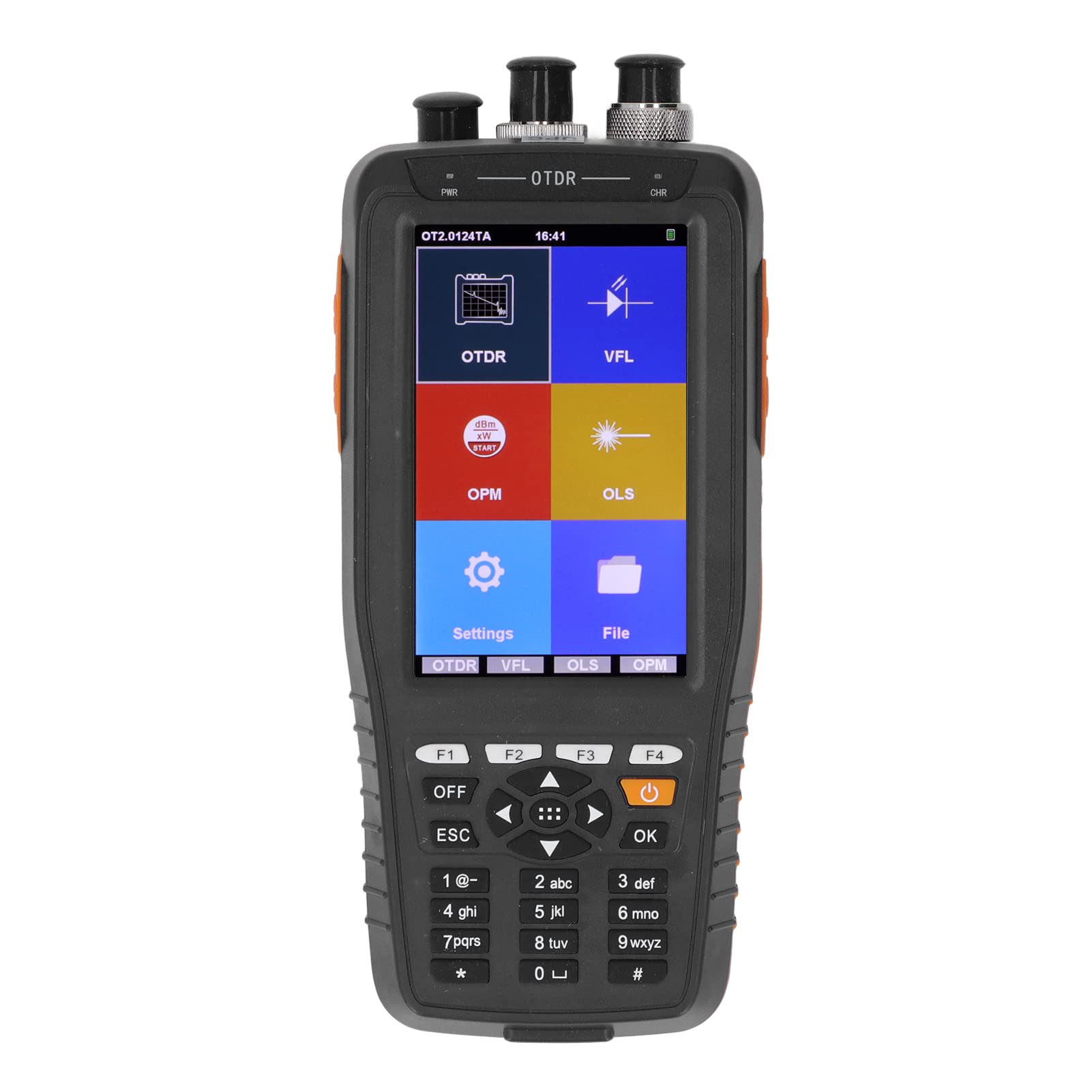
Figure 2.1: Front and bottom view of the AUA280U OTDR with labeled components.
- Optical Power Meter Port: Input for optical power measurement.
- VFL Port: Output for the Visual Fault Locator function.
- OTDR or Light Source Port: Input/output for OTDR and Optical Light Source functions.
- Power Supply Indicator: Indicates power status.
- Charging Indicator: Indicates charging status.
- LCD Display Area (Touch Screen): 3.97-inch IPS screen for displaying data and interaction.
- Soft Keys (F1-F4): Quick entry buttons for various functions.
- Power Off Button: Turns the device on/off.
- Cancellation Key (ESC): Returns to the previous screen or cancels an operation.
- Direction Selection Keys: Navigation buttons.
- Confirmation Key (OK): Confirms selections or actions.
- Keyboard Input Area: Numeric and special character input.
- Data Transfer Port: USB interface for connecting to a computer.
- Charging Port: For connecting the power adapter.
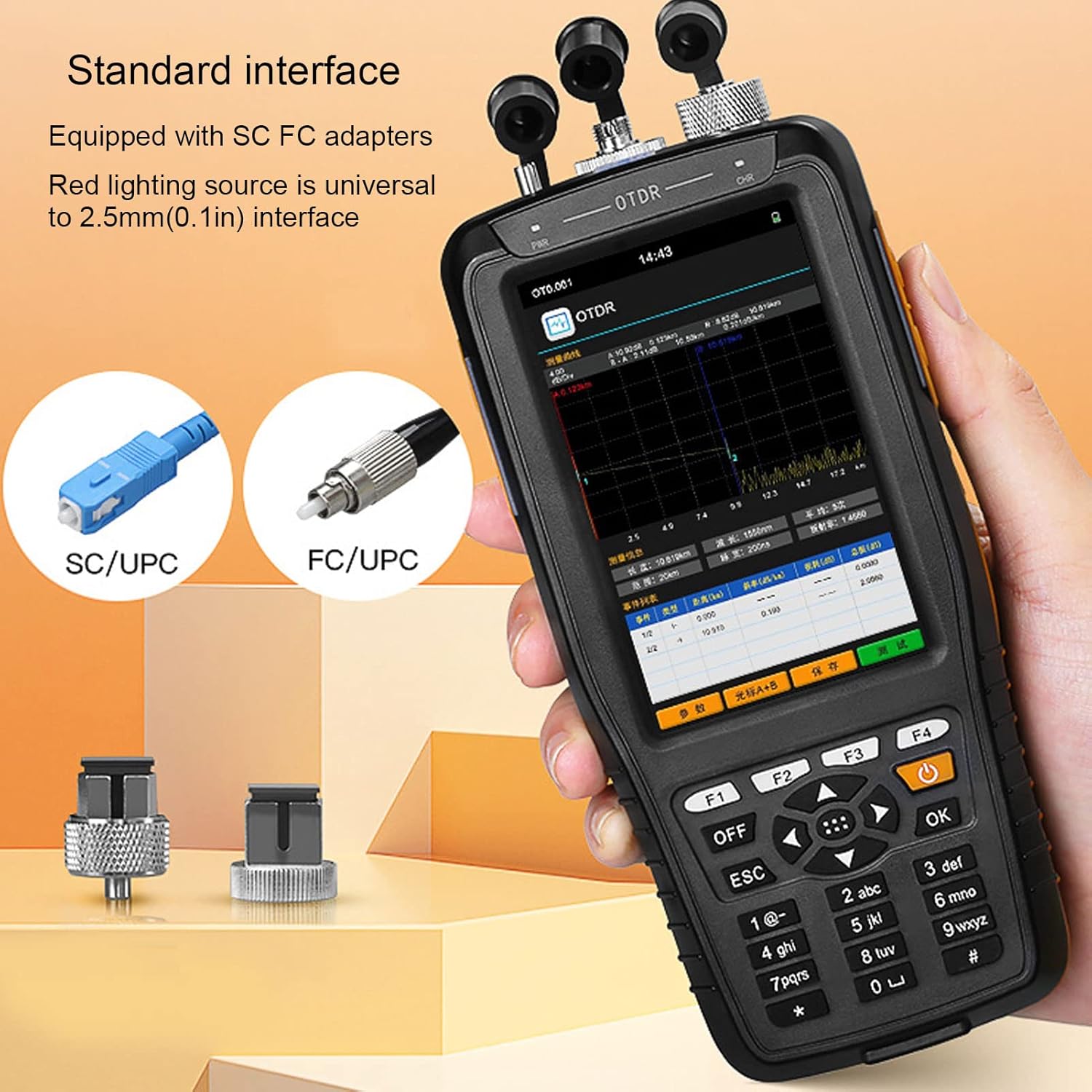
Figure 2.2: Standard interface with SC/UPC and FC/UPC adapters. The red lighting source is compatible with 2.5mm (0.1in) interfaces.
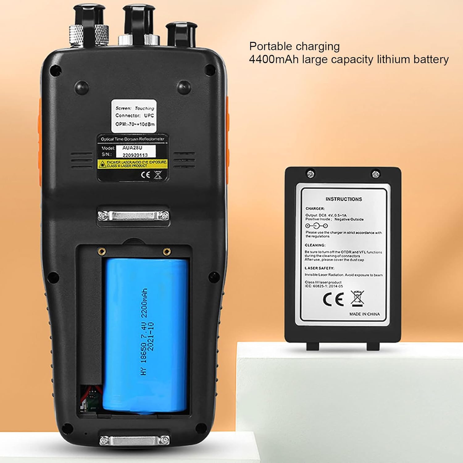
Figure 2.3: Rear view showing the 4400mAh large capacity lithium battery for portable charging.

Figure 2.4: Included accessories: power adapter, USB cable, lanyard, SC connector, FC connector, cleaning swabs, and storage bag.
3. Specifications
| Feature | Specification |
|---|---|
| Model | AUA280U |
| Connector Type | UPC (FC or PC, SC or PC; FC or APC, SC or APC optional) |
| Material | ABS |
| Product Voltage | 100-240V |
| Input Voltage | 8.4V 0.5-1A |
| Display | 3.97 inch IPS Touch Screen, 800 x 480 pixels |
| Power Supply | 7.4V 4400mAh Li-ion Battery (integrated) |
| Data Storage | 200 groups |
| Unit | Meter, Inch, Mile |
| OTDR Function | |
| Wavelength | 1310/1550nm (24/22dB), 1310/1550nm (26/24dB), 1550nm (20dB), 1610nm (20dB) |
| Dynamic Range | 24/22dB, 26/24dB, 20dB |
| Measurement Distance | 0-60km |
| Fiber Optic Connector Type | 9/125µm SM |
| Reflection Blind Zone | 2m |
| Visual Fault Locator (VFL) | |
| Wavelength | 650nm |
| Output Power | ≥10mW |
| Mode | CW, 1Hz, 2Hz |
| Fiber Type | SM, MM |
| Optical Power Meter (OPM) | |
| Measurement Range | -70-+10dBm |
| Wavelength Range | 800-1650nm |
| Calibration Wavelength | 850, 1300, 1310, 1490, 1550, 1625 |
| Detector Type | InGaAs |
| Connector | FC or PC, SC or PC interchangeable (ST optional) |
| Optical Light Source (OLS) | |
| Emitter | FP LD |
| Wavelength | 1310/1550nm |
| Connector | FC or PC (SC or ST optional) |
| Output Power | ≥ -5dBm |
| Fiber Type | SM |
4. Setup
4.1 Unpacking and Inspection
Carefully unpack the AUA280U OTDR and all accessories. Verify that all items listed in the package contents are present and undamaged. If any items are missing or damaged, contact your supplier immediately.
4.2 Charging the Battery
- Connect the provided power adapter to the charging port on the device.
- Plug the power adapter into a standard electrical outlet (100-240V).
- The charging indicator light will illuminate. Allow the device to charge fully before first use. A full charge typically takes several hours.
4.3 Powering On/Off
- To power on: Press and hold the Power Off button until the screen illuminates.
- To power off: Press and hold the Power Off button until the shutdown prompt appears, then confirm.
5. Operating Instructions
The AUA280U features a touch screen interface for easy navigation. Alternatively, the physical buttons can be used.
5.1 OTDR Function
The OTDR function is used for measuring fiber length, identifying breaks, and analyzing optical network performance.
- From the main menu, tap the 'OTDR' icon or press the corresponding soft key.
- Connect the fiber optic cable to be tested to the OTDR port using the appropriate connector (e.g., FC/UPC, SC/UPC). Ensure connectors are clean.
- Select the desired wavelength (e.g., 1310nm, 1550nm) and measurement parameters (e.g., range, pulse width) from the settings menu.
- Initiate the test. The OTDR trace will be displayed on the screen, showing events like splices, connectors, and fiber ends.
- Analyze the trace for event locations, loss, and reflection. The device software allows for further data analysis and report generation.
5.2 Visual Fault Locator (VFL) Function
The VFL emits a visible red laser light to quickly locate breaks, bends, or poor connections in fiber optic cables over short distances.
- From the main menu, tap the 'VFL' icon or press the corresponding soft key.
- Connect the fiber optic cable to the VFL port.
- Select the desired mode (CW for continuous wave, 1Hz or 2Hz for flashing).
- Activate the VFL. Observe the fiber for any visible red light leakage, indicating a fault.
- Caution: Avoid direct eye exposure to the VFL laser light.
5.3 Optical Power Meter (OPM) Function
The OPM measures the absolute or relative optical power in a fiber optic link.
- From the main menu, tap the 'OPM' icon or press the corresponding soft key.
- Connect the fiber optic cable from the light source to the OPM port.
- Select the appropriate wavelength for measurement (e.g., 1310nm, 1550nm).
- The measured optical power (in dBm) will be displayed on the screen.
5.4 Optical Light Source (OLS) Function
The OLS provides a stable optical signal at specific wavelengths for testing fiber optic cables in conjunction with an OPM.
- From the main menu, tap the 'OLS' icon or press the corresponding soft key.
- Connect the fiber optic cable to the OLS port.
- Select the desired output wavelength (e.g., 1310nm, 1550nm).
- The OLS will emit a stable light signal. This can be used with an external OPM to measure insertion loss.
5.5 Data Management
The AUA280U can store up to 200 groups of data. Use the 'File' menu to save, review, or delete measurement results. Data can be transferred to a computer via the USB interface for further analysis using the provided software.
6. Maintenance
6.1 Cleaning the Device
- Regularly clean the device's exterior with a soft, dry cloth.
- For the screen, use a screen-specific cleaning solution and a microfiber cloth.
- Keep the ports free from dust and debris. Use the provided cotton swabs or specialized fiber optic cleaning tools for cleaning optical connectors and ports.
6.2 Battery Care
- To prolong battery life, avoid fully discharging the battery frequently.
- If the device will not be used for an extended period, charge it to approximately 50% and store it in a cool, dry place. Recharge every 3-6 months.
- Only use the original charger or a compatible charger specified by the manufacturer.
6.3 Storage
Store the device in its protective bag in a clean, dry environment away from direct sunlight, extreme temperatures, and corrosive chemicals.
7. Troubleshooting
| Problem | Possible Cause | Solution |
|---|---|---|
| Device does not power on | Low battery; Power button not pressed long enough; Device malfunction. | Charge the battery; Press and hold the power button for 3-5 seconds; Contact support if issue persists. |
| Inaccurate OTDR/OPM readings | Dirty connectors; Incorrect wavelength setting; Damaged fiber. | Clean all fiber optic connectors; Verify wavelength settings match the light source; Inspect fiber for damage. |
| VFL light is dim or absent | Dirty VFL port; Fiber not properly connected; VFL module malfunction. | Clean the VFL port; Ensure secure fiber connection; Contact support. |
| Touch screen unresponsive | Software glitch; Screen damage. | Restart the device; If issue persists, contact support. |
| Cannot transfer data to PC | USB cable issue; Driver not installed; Software not running. | Try a different USB cable; Install necessary drivers; Ensure analysis software is open. |
8. Warranty and Support
For warranty information and technical support, please refer to the documentation provided with your purchase or contact your vendor. Keep your proof of purchase for warranty claims.