VBESTLIFE Vbestlifeipn0xvta9c
VBESTLIFE X79G A Mainboard User Manual
Model: Vbestlifeipn0xvta9c
1. Introduction
This manual provides comprehensive instructions for the installation, operation, and maintenance of your VBESTLIFE X79G A Mainboard. This M ATX computer mainboard is designed for DIY computer enthusiasts, offering robust performance with support for M.2 interface, SATA2.0, Gigabit Network Card, 4xDDR3 memory slots, and 12xUSB2.0 ports. Please read this manual thoroughly before proceeding with installation to ensure proper setup and functionality.
2. Product Overview
The VBESTLIFE X79G A Mainboard is built with a PCB board for long-term stability and features a high-capacity power supply for smooth program execution. It supports a range of Intel Xeon E5 V1/V2 and Core CPUs.

Figure 2.1: VBESTLIFE X79G A Mainboard. This image displays the overall layout of the motherboard, including the LGA2011 CPU socket, four DDR3 memory slots (green), PCIe x16 slot, SATA ports, and USB headers.
2.1 Key Features
- M.2 Interface: Equipped with an NVME M.2 compatible interface, offering theoretical bandwidth up to 4GB/s.
- Durable PCB Board: Constructed with a high-quality PCB board to ensure long-term stability and prevent deformation.
- CPU Support: Features an X79G A server chip, supporting Intel Xeon E5 V1/V2 and Core CPUs (e.g., Xeon E5 4650, E5 2640 v2, E5 2670 v2, Core i7 3930K, i7 4960X).
- SATA 2.0 Slots: Includes SATA 2.0 slots for efficient data transfer.
- PCIe 3.0X16 Graphics Card Slot: Provides a dedicated slot for high-performance graphics cards.
- Gigabit Ethernet: Integrated Gigabit Network Card for high-speed network connectivity.
- Solid Capacitors: Utilizes all solidly state capacitors for stable power supply and enhanced stability.

Figure 2.2: All Solidly Capacitors. This image highlights the solid-state capacitors on the motherboard, which contribute to stable performance and extended lifespan.

Figure 2.3: Motherboard Interface Layout. This diagram provides a detailed view of the motherboard's various interfaces, including Front USB 2.0x2, DDR3x4 memory slots, 8PIN CPU power connector, LGA2011 CPU Slot, 24PIN motherboard power connector, SATA2.0x4, 4PIN CPU Fan Pin, M.2 NVME interface, PCIe 16X slot, Gigabit NIC x 1, and 5.1 Channel audio.
3. Setup and Installation
Proper installation is crucial for the optimal performance of your mainboard. Ensure you have all necessary components and tools before beginning.
3.1 Package Contents
- 1 x DDR3 Mainboard (with inbuilt CR2032 240mah battery)
- 1 x Metal Plate (I/O Shield)
- 1 x Connection Cable (SATA cable)
- 1 x User Manual (this document)

Figure 3.1: Mainboard and Accessories. This image shows the VBESTLIFE X79G A Mainboard alongside the included metal I/O shield and connection cable (SATA cable).
3.2 Component Installation Steps
- Prepare the Case: Ensure your computer case is ready for motherboard installation. Install the I/O shield into the case's rear opening.
- Install the CPU: Carefully open the CPU socket retention arm. Align the CPU with the socket (matching the golden triangle on the CPU to the triangle on the socket) and gently place it into the LGA2011 socket. Close the retention arm to secure the CPU.
- Install the CPU Cooler: Apply thermal paste to the CPU if not pre-applied on the cooler. Mount the CPU cooler according to its specific instructions, ensuring it is securely fastened and the fan cable is connected to the CPU_FAN header on the motherboard.
- Install RAM (DDR3 Memory): Open the clips on the DDR3 memory slots. Align the memory modules with the slots, ensuring the notch on the module matches the key in the slot. Press down firmly on both ends until the clips snap into place. For dual-channel performance, install memory in matching colored slots (e.g., DIMM1 and DIMM2).
- Install M.2 NVME SSD (Optional): If using an M.2 NVME SSD, insert it into the M.2 slot at an angle, then gently push it down and secure it with the provided screw.
- Install Graphics Card (Optional): Open the retention clip on the PCIe 16X slot. Align your graphics card with the slot and press down firmly until it clicks into place. Secure it with a screw to the case.
- Connect Storage Drives (SATA): Connect your SATA hard drives or SSDs to the SATA2.0 ports on the motherboard using SATA data cables. Connect the power cables from your power supply to these drives.
- Connect Power Supply: Connect the 24-pin ATX power connector from your power supply to the main 24-pin power socket on the motherboard. Connect the 8-pin CPU power connector to the 8-pin socket near the CPU.
- Connect Front Panel Cables: Connect the power button, reset button, USB ports, audio jacks, and LED indicators from your case's front panel to the corresponding headers on the motherboard. Refer to your case manual for specific pin assignments.
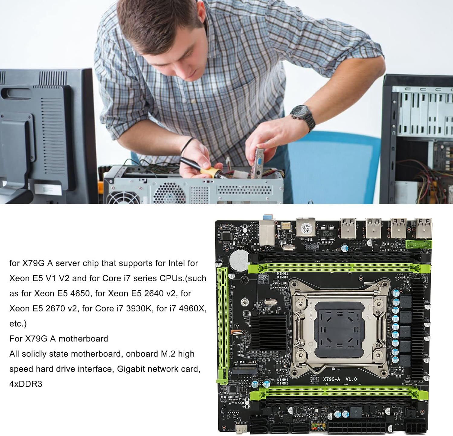
Figure 3.2: Component Installation. This image illustrates the process of installing components onto a motherboard, emphasizing careful handling and proper alignment.
4. Operating Instructions
Once all components are installed and connected, you can power on your system.
4.1 First Boot
- Ensure all power cables are securely connected and the power supply switch is in the ON position.
- Press the power button on your computer case.
- The system should boot and display the BIOS/UEFI screen or begin the operating system installation process.
4.2 BIOS/UEFI Setup
During the initial boot, you may need to enter the BIOS/UEFI setup to configure boot order, system time, or other settings. Typically, you can access this by pressing the DEL or F2 key repeatedly during startup.
4.3 Driver Installation
After installing your operating system, install the necessary drivers for the motherboard's chipset, network card, audio, and any other integrated components. These drivers are usually provided on a CD/DVD with the motherboard or can be downloaded from the manufacturer's website.
5. Maintenance
Regular maintenance helps ensure the longevity and stable operation of your mainboard.
- Dust Removal: Periodically open your computer case and use compressed air to remove dust buildup from the motherboard, CPU cooler, and other components. Dust can impede airflow and lead to overheating.
- Check Connections: Ensure all cables (power, SATA, front panel) are securely seated. Loose connections can cause intermittent issues.
- BIOS/UEFI Updates: Check the manufacturer's website for BIOS/UEFI updates. These updates can improve compatibility, stability, and performance. Follow the update instructions carefully to avoid damaging the motherboard.
- Component Contact Cleaning: If experiencing issues, carefully remove memory modules, the CPU, and graphics card. Gently wipe their metal contacts (the gold-plated pins) with a clean, soft eraser to remove any oxidation or residue, then reinsert them firmly.
6. Troubleshooting
If you encounter issues after installation or during operation, consider the following troubleshooting steps:
6.1 Common Issues and Solutions
- No Display/No Boot:
- Ensure the monitor is connected to the graphics card (or integrated graphics) and powered on.
- Verify all power cables (24-pin ATX, 8-pin CPU, GPU PCIe power) are securely connected.
- Reseat RAM modules. Try booting with only one RAM module installed.
- Reseat the graphics card.
- Perform a CMOS reset (see 6.2).
- No Network Connectivity:
- Ensure the Ethernet cable is properly connected to the motherboard's LAN port and your router/modem.
- Install or update the network card drivers.
- Check network settings in your operating system.
- No Sound:
- Ensure speakers/headphones are correctly plugged into the audio jacks.
- Install or update audio drivers.
- Check sound settings in your operating system.
- System Instability/Crashes:
- Check CPU and GPU temperatures. Ensure adequate cooling.
- Verify RAM is compatible and properly seated. Run a memory diagnostic tool.
- Ensure power supply is sufficient for all components.
- Update all drivers and BIOS/UEFI.
6.2 Resetting CMOS (Factory Settings)
If you experience persistent issues, resetting the CMOS (Complementary Metal-Oxide-Semiconductor) can revert BIOS settings to their factory defaults, which can resolve configuration-related problems.
- Power Off: Turn off your computer and unplug the power cord from the wall outlet.
- Locate CMOS Battery: Find the small, coin-sized battery (CR2032) on the motherboard.
- Remove Battery: Gently remove the battery from its holder.
- Wait: Wait for 5-10 minutes to ensure all residual power is drained.
- Reinsert Battery: Place the CMOS battery back into its holder, ensuring correct polarity.
- Power On: Plug in the power cord and power on your computer. You may need to reconfigure basic BIOS settings like date and time.
7. Specifications
Detailed technical specifications for the VBESTLIFE X79G A Mainboard.
| Feature | Specification |
|---|---|
| Item Type | DDR3 Mainboard |
| Material | PCB |
| Motherboard Board Type | M ATX |
| Motherboard Size | Approx. 190 x 190mm / 7.5 x 7.5in |
| Graphics Card Slot | 1xPCIE 16X (PCIe 3.0X16) |
| Network Card | Gigabit Network Card |
| CPU Socket Type | LGA2011 V1/V2 |
| Number of Memory Slots | 4xDDR3 |
| Memory Capacity Maximum | 128GB |
| Hard Disk Interface | 4xSATA2.0 |
| Power Connector | 1x8pin, 1x24pin |
| USB Interface | 12xUSB2.0 (8xUSB2.0 Rear Interface) |
| Expansion Interface | 1xNVME M.2 Interface |
| Built-in Battery | CR2032x1 240mah |
| Item Weight | 1.42 pounds |
| Product Dimensions | 7.5 x 7.5 x 7.5 inches |
8. Warranty and Support
For warranty information and technical support, please refer to the documentation provided with your purchase or visit the official VBESTLIFE website. Keep your proof of purchase for warranty claims.
If you require further assistance, please contact VBESTLIFE customer support through their official channels.
Related Documents - Vbestlifeipn0xvta9c
 |
VBESTLIFE M.2 A+E Gigabit Ethernet Network Card with I210AT Chip - Product Manual Product manual for the VBESTLIFE M.2 A+E Gigabit Ethernet Network Card featuring the I210AT chipset. Details specifications, features, and package contents for industrial and embedded computer applications. |
 |
Product Manual: Computer Accessories CEB32673.1 User manual for the CEB32673.1 computer accessory. Includes manufacturer details, EU representative contact, safety compliance, and usage instructions. |
 |
VBESTLIFE Expansion Card User Manual User manual for the VBESTLIFE Expansion Card (Model 21546286), including manufacturer details, EU representative information, compliance warnings, and setup instructions. |
 |
VBESTLIFE DIY Small Wind Turbine Generator Kit Specifications Technical specifications and features for the VBESTLIFE DIY small wind turbine generator, a compact educational tool for science models and wind power demonstration. |
 |
VBESTLIFE Computer Camera User Manual User manual for the VBESTLIFE Computer Camera (Model 965421536), including manufacturer details, EU representative information, safety warnings, and initial usage instructions. |
 |
User Manual: Copper Water Cooling Block (DS01520) User manual and technical specifications for the DS01520 Copper Water Cooling Block for GPU and CPU, including manufacturer and compliance information. |
Ask a question about this manual
Ask about setup, troubleshooting, compatibility, parts, safety, or missing instructions. Manuals+ will review the question and use this page’s manual context to help answer it.