1. Introduction
This manual provides detailed instructions for the installation, configuration, operation, and maintenance of the Generic P8H61-M LX motherboard. Please read this manual thoroughly before attempting any installation or configuration to ensure proper setup and safe operation.
2. Safety Information
Always observe the following safety precautions when handling the motherboard or any computer components:
- Ensure the power supply is disconnected from the wall outlet before installing or removing any components.
- Wear an anti-static wrist strap or frequently touch a grounded metal object to discharge static electricity, which can damage electronic components.
- Handle the motherboard by its edges to avoid touching sensitive components.
- Keep the motherboard and components away from moisture and extreme temperatures.
- Refer to the power supply unit's manual for specific safety guidelines related to power connections.
3. Package Contents
Verify that all items are present in your motherboard package. If any item is damaged or missing, contact your vendor.
- Generic P8H61-M LX Motherboard
- I/O Shield
- SATA Data Cable(s)
- User Manual (this document)
4. Product Overview
The Generic P8H61-M LX is an LGA 1155 socket motherboard designed to support Intel 2nd and 3rd Generation Core Processors. It features DDR3 memory support and a PCI Express x16 slot for graphics cards.
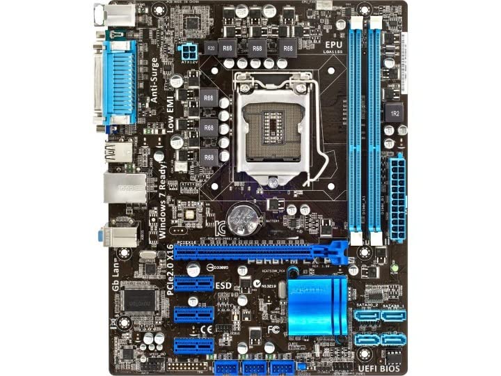
Figure 4.1: Motherboard Layout. This image displays the top-down view of the P8H61-M LX motherboard, highlighting key components such as the LGA 1155 CPU socket, two DDR3 DIMM slots, one PCIe 2.0 x16 slot, two PCIe x1 slots, four SATA ports, 24-pin ATX power connector, and 4-pin CPU power connector. Various headers for front panel connections are also visible.
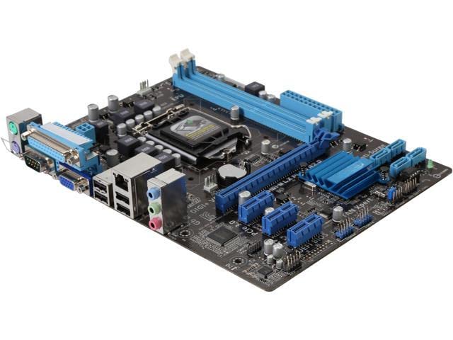
Figure 4.2: Angled Motherboard View. An angled perspective of the P8H61-M LX motherboard, providing a clearer view of the rear I/O panel and the overall component placement, including the chipset heatsink and various onboard connectors.

Figure 4.3: Rear I/O Panel. This image details the rear input/output ports of the P8H61-M LX motherboard. From left to right, it includes two PS/2 ports (for keyboard and mouse), one VGA port, one DVI-D port, four USB 2.0 ports, one RJ45 LAN port, and three audio jacks (Line In, Line Out, Microphone).
5. Setup and Installation
Follow these steps to properly install your motherboard and its components.
5.1. CPU Installation
- Locate the LGA 1155 CPU socket on the motherboard.
- Gently push down the load lever and pull it to the side to open the CPU socket cover.
- Carefully align the CPU with the socket, ensuring the golden triangle on the CPU matches the triangle mark on the socket. Do not force the CPU into the socket.
- Close the socket cover and push the load lever back into its locked position.
- Install the CPU cooler according to its manufacturer's instructions, ensuring proper thermal paste application.
5.2. Memory (RAM) Installation
- Locate the two DDR3 DIMM slots.
- Open the clips at both ends of the DIMM slot.
- Align the memory module with the slot, ensuring the notch on the module matches the key in the slot.
- Press down firmly on both ends of the memory module until the clips snap into place.
5.3. Expansion Card Installation
- Identify the appropriate PCI Express slot (e.g., PCIe 2.0 x16 for a graphics card).
- Remove the corresponding expansion slot cover from your PC case.
- Align the expansion card with the slot and press down firmly until it is securely seated.
- Secure the card with a screw to the PC case.
5.4. Storage Device Connection
- Connect one end of a SATA data cable to a SATA port on the motherboard.
- Connect the other end of the SATA data cable to your storage device (HDD/SSD).
- Connect a SATA power cable from your power supply unit to the storage device.
5.5. Power Supply Connection
- Connect the 24-pin ATX main power connector from your power supply to the corresponding header on the motherboard.
- Connect the 4-pin CPU power connector (ATX 12V) from your power supply to the header near the CPU socket.
5.6. Front Panel Connections
Connect the cables from your PC case's front panel (power button, reset button, HDD LED, power LED, front USB, front audio) to the corresponding headers on the motherboard. Refer to the motherboard diagram (Figure 4.1) for header locations and your PC case manual for cable identification.
5.7. Rear Panel Connections
Connect your peripherals (keyboard, mouse, monitor, network cable, speakers) to the appropriate ports on the motherboard's rear I/O panel (Figure 4.3).
6. Operating System Installation
After assembling your system, install your preferred operating system. Insert the OS installation media (USB drive or DVD) and boot from it. Follow the on-screen instructions to complete the installation. Ensure you install all necessary drivers for the motherboard chipset, audio, and LAN from the manufacturer's website or provided media.
7. BIOS/UEFI Setup
To access the BIOS/UEFI setup utility, press the designated key (commonly DEL or F2) during the system's power-on self-test (POST). Within the BIOS/UEFI, you can configure boot order, system time, CPU settings, memory settings, and other hardware parameters.
8. Maintenance
Regular maintenance helps ensure the longevity and stable operation of your motherboard:
- Cleaning: Periodically clean dust from the motherboard and components using compressed air. Ensure the system is powered off and unplugged before cleaning.
- Connections: Verify that all cables and expansion cards are securely seated.
- BIOS/Drivers: Keep your BIOS/UEFI firmware and device drivers updated to the latest versions available from the manufacturer to improve compatibility and performance.
9. Troubleshooting
If you encounter issues, consider the following common troubleshooting steps:
- No Power: Check all power connections (24-pin ATX, 4-pin CPU, power supply switch, wall outlet).
- No Display: Ensure the monitor is connected to the correct graphics output (onboard or discrete GPU) and is powered on. Reseat the graphics card and RAM modules.
- System Fails to Boot: Check CPU, RAM, and power connections. Try booting with minimal components (CPU, one RAM stick, graphics card if no integrated graphics).
- Operating System Not Loading: Verify boot order in BIOS/UEFI. Check SATA cable connections to storage devices.
- Peripheral Issues: Ensure drivers are installed. Try connecting peripherals to different ports.
10. Specifications
| Feature | Specification |
|---|---|
| Brand | Generic |
| Model | P8H61-M LX |
| CPU Socket | LGA 1155 |
| Compatible Processors | Intel 2nd Generation Core Processors (Sandy Bridge), Intel 3rd Generation Core Processors (Ivy Bridge) |
| Chipset | Intel H61 Express |
| Memory Slots | 2 x DDR3 DIMM |
| Max Memory Capacity | 16 GB |
| Memory Type | DDR3 |
| Graphics Interface | 1 x PCI Express 2.0 x16 |
| Expansion Slots | 2 x PCI Express x1 |
| Storage Ports | 4 x SATA |
| USB Ports (Rear) | 4 x USB 2.0 |
| Video Output | 1 x VGA, 1 x DVI-D |
| LAN | 1 x RJ45 (Gigabit LAN) |
| Audio | 3 x Audio Jacks |
| Dimensions (LxWxH) | 25 x 22 x 5 cm (approximate) |
11. Warranty Information
This Generic P8H61-M LX motherboard comes with a 1-year warranty from the date of purchase. The warranty covers defects in materials and workmanship under normal use. Please retain your proof of purchase for warranty claims. The warranty does not cover damage caused by improper installation, misuse, accidents, unauthorized repairs, or natural disasters.
12. Support
For technical assistance or further inquiries regarding your Generic P8H61-M LX motherboard, please contact your vendor or the point of purchase. Ensure you have your product model number and purchase details ready when seeking support.