1. Introduction
Thank you for choosing the JOPIX Doris CB Radio Station. This manual provides detailed instructions for the proper installation, operation, and maintenance of your new CB radio. Please read this manual thoroughly before using the device to ensure optimal performance and safety.
The JOPIX Doris is a versatile 40-channel CB radio operating on AM/FM modes with 4W output power. It features Automatic Squelch Control (ASQ), Roger Beep, and VOX functionality, and is compatible with 12-24V power systems.
2. Safety Information
Always observe the following safety precautions to prevent damage to the device or injury to yourself:
- Do not expose the unit to rain, moisture, or extreme temperatures.
- Ensure proper ventilation to prevent overheating.
- Connect the radio to a power source within the specified voltage range (12-24V DC). Incorrect voltage can damage the unit.
- Do not attempt to open or modify the radio. Refer all servicing to qualified personnel.
- Use only the antenna and accessories recommended by the manufacturer.
- Avoid operating the radio in areas where radio transmissions are prohibited or could cause interference.
3. Package Contents
Verify that all items are present in the package:
- JOPIX Doris CB Radio Unit
- Microphone
- Mounting Bracket and Screws
- Power Cable
- User Manual (this document)

Figure 3.1: Included components of the JOPIX Doris CB Radio Station.
4. Product Overview
4.1 Front Panel

Figure 4.1: Front panel of the JOPIX Doris CB Radio.
- POWER Button: Turns the radio on/off.
- MT/LOCK Button: Momentary Tune / Keypad Lock function.
- Display: Shows channel, frequency, mode, signal strength, and other indicators.
- Channel Knob: Rotates to select channels.
- SQ/M1 Button: Squelch control / Memory 1.
- VOX Button: Voice Operated Exchange activation.
- ASQ/M2 Button: Automatic Squelch Control / Memory 2.
- CH/M3 Button: Channel selection / Memory 3.
- A/F Button: AM/FM mode selection.
- TSQ/M4 Button: Tone Squelch / Memory 4.
- SCAN Button: Initiates channel scanning.
- EMG Button: Emergency channel access.
- Microphone Jack: For connecting the supplied microphone.
4.2 Rear Panel

Figure 4.2: Rear panel of the JOPIX Doris CB Radio.
- Antenna Connector (SO-239): For connecting your CB antenna.
- External Speaker Jack: For connecting an optional external speaker.
- Power Input: For connecting the 12-24V DC power cable.
5. Setup and Installation
Proper installation is crucial for optimal performance and safety. It is recommended to have the radio installed by a qualified technician if you are unsure about any steps.
5.1 Mounting the Radio
The JOPIX Doris can be mounted using the supplied mounting bracket. Choose a location that is easily accessible, provides good ventilation, and does not obstruct driving visibility or safety features.
- Secure the mounting bracket to a stable surface using the provided screws.
- Slide the radio into the bracket and secure it with the side knobs.

Figure 5.1: Example of radio mounting.
5.2 Power Connection
Connect the supplied power cable to the radio's power input. The red wire is positive (+), and the black wire is negative (-). Connect the red wire to a fused 12-24V DC positive power source (e.g., vehicle battery or power supply) and the black wire to a good ground point.
- Ensure the power source can provide sufficient current for the radio (typically 2-3 Amps).
- Install an appropriate fuse (e.g., 3A) in the positive power line, close to the power source.
5.3 Antenna Connection
Connect a properly tuned CB antenna to the SO-239 connector on the rear of the radio. A well-tuned antenna is critical for optimal performance and to prevent damage to the radio's transmitter.
- Always connect the antenna before powering on the radio.
- Regularly check the Standing Wave Ratio (SWR) of your antenna system. An SWR reading above 2.0:1 can indicate a problem and may damage the radio.
5.4 Microphone Connection
Plug the microphone cable into the microphone jack on the front panel of the radio. Ensure the connector is fully seated.
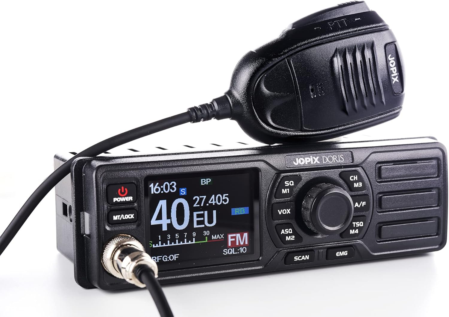
Figure 5.2: Microphone connected to the radio.
6. Operating Instructions
6.1 Power On/Off
Press the POWER button to turn the radio on. Press it again to turn the radio off.
6.2 Volume Control
Rotate the main knob (often combined with the power button) clockwise to increase volume and counter-clockwise to decrease volume.
6.3 Channel Selection
Rotate the Channel Knob to select the desired channel (1-40). Alternatively, use the CH/M3 button for channel navigation or memory recall.
6.4 AM/FM Mode Selection
Press the A/F button to switch between AM (Amplitude Modulation) and FM (Frequency Modulation) modes. The selected mode will be indicated on the display.
6.5 Squelch Control (SQ / ASQ)
- Manual Squelch (SQ): Press the SQ/M1 button. Rotate the channel knob to adjust the squelch level. This eliminates background noise when no signal is present. Adjust it just enough to silence the static.
- Automatic Squelch Control (ASQ): Press the ASQ/M2 button to activate or deactivate ASQ. ASQ automatically adjusts the squelch level for optimal reception, simplifying operation.
6.6 VOX Function
Press the VOX button to activate the Voice Operated Exchange function. When VOX is active, the radio will transmit automatically when you speak into the microphone, without needing to press the PTT (Push-To-Talk) button. Adjust VOX sensitivity as needed.
6.7 Roger Beep
The JOPIX Doris features a Roger Beep. This is a short tone transmitted automatically at the end of your transmission, signaling to other users that you have finished speaking. This feature is typically enabled by default or can be toggled via a menu setting (refer to advanced settings if available).
6.8 Scan Function
Press the SCAN button to initiate channel scanning. The radio will automatically scan through channels and stop on an active channel. Press SCAN again to stop scanning.
6.9 Emergency Channel (EMG)
Press the EMG button to quickly switch to the designated emergency channel (typically Channel 9 for emergency communications). Press it again to return to the previous channel.
7. Maintenance
- Cleaning: Use a soft, dry cloth to clean the radio's exterior. Do not use abrasive cleaners or solvents.
- Connections: Periodically check all cable connections (power, antenna, microphone) to ensure they are secure and free from corrosion.
- Antenna SWR: Regularly check your antenna's SWR, especially after any changes to the antenna system or vehicle.
- Storage: If storing the radio for an extended period, disconnect it from power and store it in a cool, dry place.
8. Troubleshooting
| Problem | Possible Cause | Solution |
|---|---|---|
| Radio does not power on. | No power connection; Blown fuse; Incorrect voltage. | Check power cable connection; Check/replace fuse; Verify power source voltage (12-24V DC). |
| No reception or poor reception. | Antenna not connected; High SWR; Squelch set too high; Incorrect mode (AM/FM). | Ensure antenna is connected; Check SWR; Adjust squelch level; Verify AM/FM mode. |
| Cannot transmit. | Microphone not connected; PTT button faulty; High SWR; Radio in receive-only mode. | Check microphone connection; Test PTT button; Check SWR; Ensure radio is not in a receive-only state. |
| Excessive static/noise. | Squelch set too low; Electrical interference; Poor antenna grounding. | Increase squelch level; Identify and mitigate interference sources; Check antenna grounding. |
9. Specifications
- Brand: Jopix
- Model: PNI-DORIS-CB
- Channels: 40 CH
- Modes: AM/FM
- Output Power: 4W
- Frequency Range: 26.965-27.405 MHz
- Voltage: 12-24 Volts (DC)
- Special Features: ASQ (Automatic Squelch), Roger Beep, VOX
- Tuner Technology: UHF
- Dimensions: 18.5 x 8.5 x 5.5 cm
- Weight: 0.84 Kilograms
- Included Components: Main unit, Microphone, Mounting Hardware
10. Warranty and Support
For warranty information, technical support, or service inquiries, please refer to the documentation provided with your purchase or contact your authorized dealer. Keep your proof of purchase for warranty claims.
Manufacturer: ONLINESHOP SRL