1. Introduction
The LianGSanSan H807SA LED Controller is designed for advanced pixel control applications. It features 8 output ports, capable of controlling a maximum of 8192 pixels. The controller supports the Art-Net protocol and can be integrated with DMX consoles for comprehensive lighting control. It also allows for setting addresses for DMX chips and managing DAT files via LAN.
2. Supported Driver Chips
The H807SA controller supports a wide range of driver chips, including but not limited to: DMX512, HDMX, DMX512_RDM, APA102, APA102-65536, WS2801, WS2811, WS2812, WS2813, TM1812, TM1809, TM1804, TM1923, TM1934, TM1925D, TM1926D, TM1803, TM1814, TM1913, TM1914, TM1926, UCS1903, UCS1909, UCS1912, UCS2903, UCS2909, UCS2912, UCS8904, UCS5603, SK9816, SK6812, SM16716, SM16703, SM16709, SM16712, SM16704, LPD6803, LPD8806, LPD1882, LPD1889, LPD1883, INK1003, APA104, P943, LC8812, GW6205, QED3110, D9866E, D9866B, D9865C, D9865E, D9865F, D9864B, D9864C.
3. Key Features
- Eight Output Ports: Controls a maximum of 4096 pixels, with each port supporting up to 1024 pixels.
- SD Card Support: Compatible with FAT32 and FAT16 formats, allowing storage of up to 64 DAT files.
- LAN Synchronous Control: Enables synchronized operation across multiple controllers and UDP file switching.
- DMX Console Connectivity: Supports RGBW communication, allowing for file changes, speed, and brightness adjustments with fast response.
- Art-Net Protocol Support: Direct compatibility with Art-Net software such as Madrix and Jinx.
- Power-On Encryption: Features an encryption function to limit power-on times.
- DMX Chip Addressing: Includes functions for counting points and internal control testing.
- Flexible Connectivity: Can be directly connected to a computer network card, router, or a main controller.
- Online Firmware Upgrade: Supports convenient online updates for the controller's firmware.
- DAT File Sculpt Settings: Allows for DAT files with various shapes.
- W Channel Insertion: Capability to insert a 'W' channel for RGBW control.
- 16-Port Output: TM1812 and simultaneous sequence chips can output to 16 ports.
4. Setup
- Power Connection: Connect the AC power cable to the controller's AC_IN port and to a suitable power outlet.
- SD Card Insertion: Insert the SD card containing your DAT files into the SD CARD slot on the side of the controller. Ensure the card is properly seated.
- Network Connection (Optional): For LAN synchronization or Art-Net control, connect an Ethernet cable to the NET1 or NET2 port.
- DMX Connection (Optional): For DMX console control, connect your DMX console to the DMX_IN port.
- LED Output Connection: Connect your LED pixel strips or modules to the output ports (PORT1-PORT8) using the appropriate wiring.
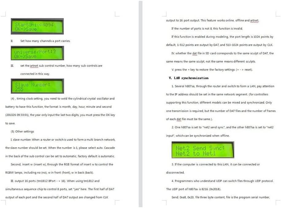
Figure 1: Rear view of the H807SA LED controller, illustrating the AC_IN, DMX_IN, DMX_OUT, NET1, and NET2 ports.

Figure 2: Side view of the H807SA LED controller, highlighting the SD card slot for file management.
5. Operating Instructions
This section details the operational steps and menu navigation for the H807SA LED Controller.
5.1 Basic Operation
- Power On: After connecting power, the display will show the file menu (e.g., "File01"), followed by the file serial number and file name on the second line.
- Speed Adjustment: Press the MENU key to access the speed menu. Adjust the speed (frames per second) within the range of 1-100. For synchronized power supplies, ensure all controllers have the same speed setting.
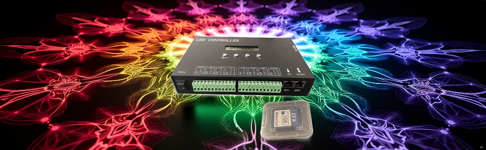
Figure 3: Controller display showing speed setting.
- Brightness Control: The next menu item is brightness, adjustable from 0-16.
Figure 4: Controller display showing brightness setting.
- Play Mode Selection: The fourth menu offers play modes: "all", "single", and "timed playback". When a DMX console signal is received, the controller automatically locks to "single file" playback.
Figure 5: Controller display showing play mode setting.
- Net2 Working Mode: For LAN synchronization, select "net2 input". If LAN synchronization is required, one controller must be set to "net2 send sync" and others to "net2 input".
Figure 6: Controller display showing Net2 working mode setting.
- IP Address Setting: The sixth menu allows setting the IP address. The first three bytes are adaptive. Ensure no duplicate IP addresses exist on the same LAN.
Figure 7: Controller display showing IP address setting.
- IC Type Selection: The seventh menu is for selecting the IC type. If no type is selected, the chip type specified in the DAT file will be used. If the DAT file does not specify a chip type, it will be invalid. For Art-Net control, if no chip model is specified, the model of the first sub-controller will be used; otherwise, your custom setting prevails.
- Port Output Mode: The eighth menu allows selecting the port output mode (245 or 485).
- DMX Address Setting: The ninth menu sets the initial DMX channel address (range 1-512).
- If the number of color components is 4 (RGBW), each controller occupies 8 channels. Otherwise, it occupies 7 channels.
- Default starting address is 1 (channels 1-7). If set to 2, it occupies channels 2-8.
- The first channel controls brightness (0-3 for off, 4-7 for 1, 8-11 for 2, up to 252-255 for 63).
- The second channel is Red, third is Green, fourth is Blue.
- If color components are less than 4, 7 channels are occupied.
- The fifth channel is the DAT file serial number. Four DMX values correspond to one file (0-3 for file 1, 4-7 for file 2, up to 252-255 for file 64).
- The sixth channel controls playback speed (calculated as (speed set by key) * (speed channel value) / 255).
- The seventh channel controls direction (0-127 for forward, other values for reverse).
- If color components are 4, the fifth channel is White.
- The sixth channel is DAT file serial number (same logic as above).
- The seventh channel is playback speed (same logic as above).
- The eighth channel is direction (same logic as above).
Figure 8: Controller display showing DMX address setting.
- Pixel Channel and Color Component Settings: Set the number of pixel channels and color components per point. Default is 3 (RGB), range is 3-4.
- Folded Menu Navigation: The eleventh menu is a folded menu. Press the OK key to select the change menu. Press OK to enter the submenu. Continue pressing MENU to switch submenus.
- Addressing Menu: This submenu allows for addressing.
- DMX IC Type Selection: Select the type of DMX IC.
- Light Channel Count: Set the number of channels occupied by a lamp or transcoding board. For point lights, this value matches the number of color components.
- DMX Chip Color Value Setting: Some DMX chips require color values (red, green, blue) to be set upon power-on. Others do not.
- DMX Chip Current Gain: Some DMX chips require current gain to be set (range 1-64).
- DMX Chip Output Format: Some DMX chips require output format to be set (e.g., Output.RZ or Output.DMX512).
- Initial Channel Address Input: Input the initial channel address and press OK. Wait a few seconds for coding to complete.
5.2 Internal Control and Art-Net Settings
- Counting Points: For internal control, count points by pressing and holding to accelerate.
- Art-Net Setting Menu: The chip model is selected from the seventh menu. The first sub-control can also be set via computer software.
- Set the starting space.
- Set the universal port.
- Set the Art-Net sub-control number, indicating how many sub-controls are connected.
5.3 Other Settings
- Timing Clock Setting: To enable this function, a cylindrical crystal oscillator and battery must be soldered. Set the time in month, day, hour, minute, second format (e.g., 201026 09:30:01, input only the last two digits for the year). Press OK to save.
- Slave Number: When using a router or switch for a multi-branch network, set the slave number. If the number is 1, select "auto". Cascading sub-controls can be set to automatic (factory default).
- RGBW Control: Insert 'W' (insert white) through the RGB format to control RGBW lamps. Options include 'no' (no white), 'w in front' (white in front), and 'w in back' (white in back).
- 16-Port Output (TM1812): For TM1812 and simultaneous sequence chips controlling 8 ports, set 'yes'. This changes the first and second half of DAT output from CLK output to 16-port output. This feature works online, offline, and with Art-Net. If the number of ports is not 8, this function is invalid. If enabled during modeling, the default port length is 1024 points (1-512 by DAT, 513-1024 by CLK).
- DAT File Sculpt Correspondence: Verify if the DAT file on the SD card corresponds to the same sculpt. "Same" means identical sculpt; "different" means different sculpts.
- Factory Reset: Press the + key to restore factory settings.
6. LAN Synchronization
- Network Configuration: When using multiple H807SA controllers with a router and switch to form a LAN, ensure all IP addresses are within the same network segment. Different models supporting this function can be mixed and synchronized. Only one transmission is required, but the number of DAT files and frames must be identical across all synchronized controllers.
- Offline Synchronization: Set one H807SA to "net2 send sync" and the others to "net2 input" for offline synchronization.
Figure 9: Controller display showing Net2 send sync setting.
- Computer Connection: A computer connected to the LAN can connect or disconnect from the controller.
- UDP Protocol for File Switching: Programmers familiar with UDP can switch files using the UDP protocol. The H807SA's UDP port is 8216 (0x2018).
- Send Command: 0xa8, 0x20, followed by three bytes for file content (program serial number, starting from 0).
- Reply: 0xa8, 0x21, followed by file content.
- Example: To switch to program 1, send hexadecimal aa2000.
- Query Program Serial Number: Send 0xa8, 0x30.
- H806SA Reply: 0xa8, 0x31, file. (File is the program serial number, 0 means program 1, 1 means program 2).
Figure 10: Example software interface for UDP communication with the controller.
7. Firmware Update
To update the firmware:
- Place the upgrade package onto the SD card.
- Insert the SD card into the controller.
- Press and hold the MENU key.
- While holding MENU, power on the controller.
- The controller will automatically initiate the upgrade process.
- After the upgrade, the controller will restart automatically, and the version number will be updated.
8. Controller Interface Definition
The H807SA controller features various input and output interfaces. Below is a general description of the common connections:
Figure 11: Detailed pinout diagram for the H807SA controller's output ports and power connections. Each port typically includes GND, CLK/D-, and DAT/D+ terminals.
The image above illustrates the pin definitions for the 8 output ports. Each port typically includes connections for Ground (GND), Clock/Data- (CLK/D-), and Data/Data+ (DAT/D+), essential for connecting various LED driver chips.
9. Specification Parameters
| Parameter | Value |
|---|---|
| Input Voltage | AC220V |
| Power Consumption | [Not Specified] |
| Maximum Load Capacity | 8192 Pixels |
| Weight | [Not Specified] |
| Working Temperature | -20°C to 85°C |
| External Dimensions (L x W x H) | [Not Specified] |
| Package Dimensions (L x W x H) | [Not Specified] |
Note: Specific values for Power Consumption, Weight, External Dimensions, and Package Dimensions were not provided in the source material. Please refer to product packaging or manufacturer's website for precise details.
10. Maintenance
- Cleaning: Regularly clean the exterior of the controller with a soft, dry cloth. Avoid using liquid cleaners or solvents.
- Ventilation: Ensure the controller is placed in a well-ventilated area to prevent overheating. Do not block ventilation openings.
- Storage: When not in use for extended periods, store the controller in a cool, dry place away from direct sunlight and extreme temperatures.
- Cable Inspection: Periodically check all connected cables for any signs of damage or wear. Replace damaged cables immediately.
11. Troubleshooting
- No Power:
- Check if the power cable is securely connected to both the controller and the power outlet.
- Verify that the power outlet is functional.
- LEDs Not Responding:
- Ensure the correct driver chip type is selected in the controller settings.
- Verify that the DAT file is valid and properly loaded from the SD card.
- Check all wiring connections between the controller and the LED strips/modules.
- Confirm that the DMX address or Art-Net settings are correctly configured.
- Synchronization Issues:
- Ensure all controllers in a LAN setup have IP addresses within the same network segment.
- Verify that one controller is set to "net2 send sync" and others to "net2 input" for offline synchronization.
- Confirm that all synchronized controllers have the same DAT files and frame counts.
- Firmware Update Failure:
- Ensure the upgrade package is correctly placed on the SD card.
- Follow the firmware update procedure precisely (holding MENU key during power-on).
12. Warranty and Support
For warranty information and technical support, please refer to the official LianGSanSan website or contact your authorized dealer. Keep your purchase receipt as proof of purchase for warranty claims.
Manufacturer: hntoolight
Seller: hntoolight
13. Product Overview Video
Video 1: A brief overview of the LianGSanSan H807SA LED Controller, showcasing its physical appearance and various ports. This video provides a visual introduction to the product.
14. Additional Product Images
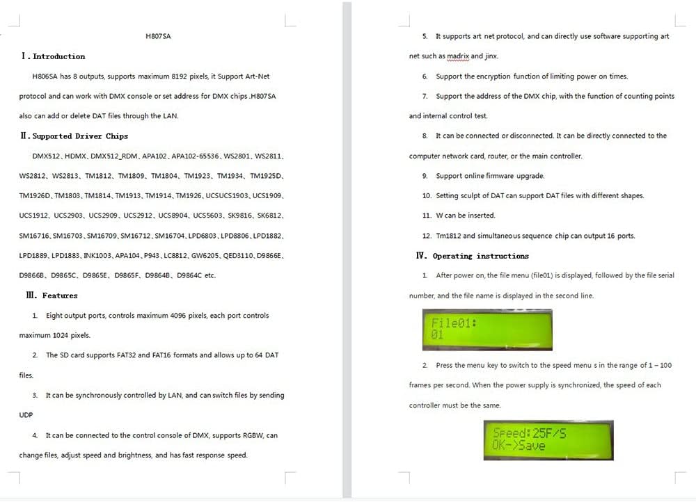
Image 1: Front view of the H807SA LED controller, highlighting the control buttons and LCD display.
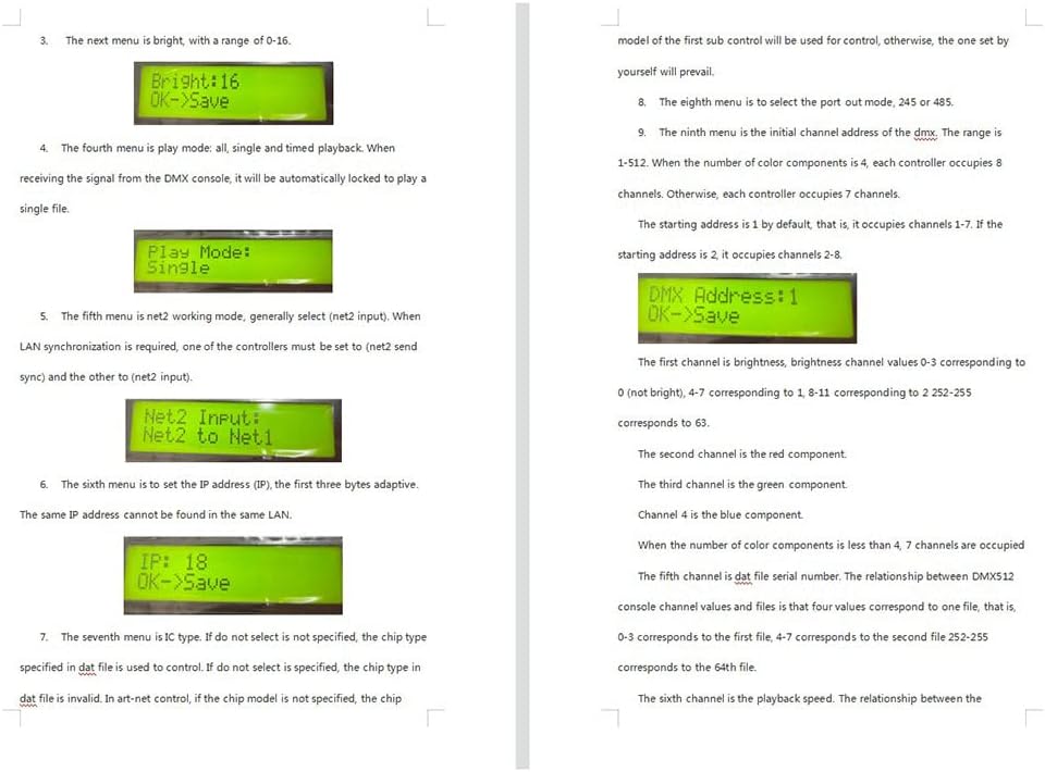
Image 2: Top-down view of the H807SA LED controller, showing the eight green output terminal blocks.

Image 3: The H807SA LED controller displayed with an SD card, indicating its use for file storage.

Image 4: A close-up of the H807SA LED controller's SD card slot, with an SD card inserted or placed nearby.

Image 5: The H807SA LED controller showcased with a dynamic, colorful LED light display in the background, illustrating its application.