Introduction
This manual provides detailed instructions for the installation and operation of the ThtRht ATX PC Case Power/Reset Switch Cable with HDD SW LED and Power Light Indicators. This universal replacement kit is designed to work with most desktop computer host cases that utilize front panel buttons, serving as an ideal replacement for old or damaged ATX power on supply reset switches.
The package includes 3 sets of PC ATX Power Reset Switch Cables, each featuring clearly labeled connectors for easy setup. The cables contain connections for HDD LED, Power LED+, Power LED-, Reset SW, and Power SW. The total cable length is approximately 68 cm (27 inches), and the LED lights are red and green.
Setup
Proper connection of the front panel cables to your motherboard is crucial for correct functionality. Each cable is clearly labeled to assist with installation. Refer to your motherboard's manual for the exact pin layout of the front panel header, as layouts can vary between manufacturers.
1. Identify Motherboard Front Panel Header
Locate the front panel header on your motherboard. This is typically a block of pins, often labeled 'F_PANEL' or similar. Consult your motherboard's user manual to identify the specific pins for Power Switch (Power SW), Reset Switch (Reset SW), Hard Drive Activity LED (HDD LED), and Power LED (Power LED+ and Power LED-).
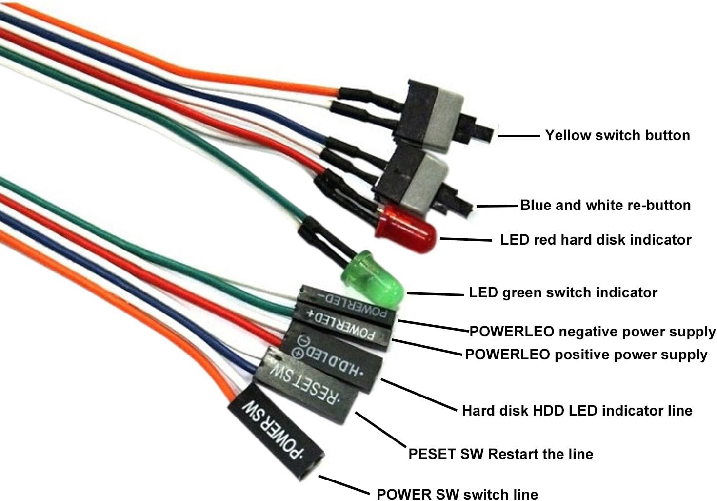
Figure 1: Labeled diagram of the PC front panel cables, showing connections for HDD LED, Power LED+, Power LED-, Reset SW, and Power SW.
2. Connect the Cables
Carefully connect each labeled cable from the kit to its corresponding pin on the motherboard's front panel header. Ensure the polarity (+/-) for the LED connections (Power LED+, Power LED-, HDD LED) is correct. The Power SW and Reset SW connections do not typically have a polarity requirement.

Figure 2: Example of PC front panel cables connected to the motherboard header.
Visual Guide: Connecting Front Panel Cables
Video 1: This video demonstrates the process of connecting front panel cables, including the power, reset, and LED indicators, to a motherboard. It provides a visual guide for proper pin alignment.
Video 2: This video shows the connection of a PC power switch cable to a motherboard. While the product in the video includes a PCIe bracket, the method for connecting the power and reset pins to the motherboard is similar and can serve as a general reference.
Operating
Once the cables are correctly connected to your motherboard, you can use the push buttons to control your computer's power and reset functions.
Power On/Off
Press the 'Power SW' button to turn on your computer. To turn off the computer, you can either perform a software shutdown through the operating system or press and hold the 'Power SW' button for a few seconds for a forced shutdown (not recommended for regular use).
Reset Function
Press the 'Reset SW' button to restart your computer. This is useful if your system becomes unresponsive.
LED Indicators
- Power LED: The Power LED (red/green) will illuminate when the computer is powered on, indicating that the system is receiving power.
- HDD LED: The HDD LED will flash to indicate hard drive activity, showing when data is being read from or written to your storage devices.
Visual Guide: Using the Power and Reset Buttons
Video 3: This video demonstrates the basic operation of a PC power button, showing how to turn on a computer using an external switch.
Video 4: This video illustrates the use of an external power button for a PC, demonstrating both power on and reset functions.
Video 5: This video shows the functionality of a PC power button, including turning the system on and off.
Maintenance
These cables require minimal maintenance. Ensure that the connections to the motherboard remain secure and free from dust or debris. Avoid excessive pulling or bending of the cables to prevent damage to the wires or connectors.
Troubleshooting
Computer Does Not Power On
- Verify that the 'Power SW' cable is correctly connected to the corresponding pins on the motherboard's front panel header.
- Ensure the power supply unit (PSU) is properly connected and switched on.
- Check all other power connections within the PC.
Reset Button Not Working
- Confirm that the 'Reset SW' cable is securely connected to the correct pins on the motherboard.
LED Indicators Not Lighting Up/Flashing
- For Power LED, ensure 'Power LED+' and 'Power LED-' cables are connected with correct polarity to the motherboard.
- For HDD LED, ensure the 'HDD LED' cable is connected with correct polarity.
- Consult your motherboard manual for specific LED pin assignments and polarity.
Specifications
- Brand: ThtRht
- Material: Copper, Polyvinyl Chloride (PVC)
- Connector Type: ATX
- Cable Length: 68 cm / 27 inches
- LED Light Number: 2
- LED Light Color: Red, Green
- Package Includes: 3 x PC ATX Power Reset Switch Cable
Warranty
This product is covered by a standard manufacturer's warranty against defects in materials and workmanship. Please retain your proof of purchase for any warranty claims. For specific warranty duration and terms, refer to the product packaging or contact the retailer.
Support
For further assistance or technical support, please contact ThtRht customer service through the retailer's platform or visit the official ThtRht website. Please have your product model number (B0BV6VCP84) and purchase details ready when contacting support.