1. Introduction
This manual provides essential information for the installation, operation, and maintenance of your HALLOMOTOR 36V-52V 1000W-1500W 35A 3-Mode Sine Wave Brushless Controller and EB06 LCD Display. Please read this manual thoroughly before use to ensure proper function and safety.
2. Product Overview
Key Features:
- Universal Voltage Support: 36V, 48V, 52V.
- Power Output: 1000W-1500W.
- Intelligent 3-mode Sine Wave Controller for smooth operation.
- Dual Mode Support: Compatible with both Hall sensor and non-Hall sensor motors.
- Self-Learning Function: Automatically adapts to motor phase combinations.
- Comprehensive Protection: Includes over/under voltage, over current, overload, overheating, anti-runaway, and locked-motor protection.
- Durable Construction: Best heat sinking with an anodized aluminum case.
Included Components:
- 1 x 15 MOSFET 35A 3-Mode Sine Wave Brushless Controller
- 1 x EB06 LCD Display

Image 2.1: The HALLOMOTOR 35A Sine Wave Brushless Controller. This unit manages power delivery to the ebike motor.

Image 2.2: The EB06 LCD Display Unit. This display provides real-time information and control for your ebike system.
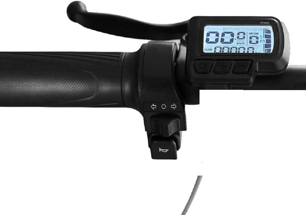
Image 2.3: The EB06 LCD Display mounted on ebike handlebars, showing its typical installation position.
3. Specifications
| Feature | Specification |
|---|---|
| Controller Rated Power | 36V 612W / 48V 816W / 52V 884W |
| Controller Peak Power | 36V 1260W / 48V 1680W / 52V 1820W |
| Controller Size | 212 x 86.5 x 48.5 mm |
| Controller Net Weight | 610 g |
| Waterproof Grade | IP65 |
| Brake Type | Low Voltage Brake |
| Rotor Position Detecting Method | Hall sensor |
| Display Type | EB06 LCD Digital Display |
4. Setup and Installation
4.1 Initial Motor Pairing (Self-Learning Function)
This process is crucial for the first-time use of the controller with your motor. Ensure the motor wheel is lifted off the ground before starting.
- Lift your ebike's motor wheel completely off the ground. This is very important to prevent unexpected movement.
- Connect the dedicated Self-Learning plug on the controller.
- Observe the motor wheel. It should begin to rotate slowly.
- Check the rotation direction:
- If the rotation direction is correct, keep the Self-Learning plug connected for 6-8 seconds, then disconnect it.
- If the rotation direction is reversed, disconnect the Self-Learning plug immediately. Reconnect it and wait for the correct rotation direction. Once correct, keep it connected for 6-8 seconds, then disconnect.
- The motor and controller pairing process is now complete.
4.2 General Installation Guidelines
- Mount the controller in a secure location, away from direct water spray and excessive heat. The aluminum case provides good heat dissipation, but proper airflow is still beneficial.
- Connect all wiring according to your ebike's specific setup. Ensure all connections are firm and properly insulated.
- Mount the EB06 display securely on your handlebars for easy visibility and access to controls.
- Verify all connections before applying power to the system.

Image 4.1: The HALLOMOTOR Ebike Controller showing its various wiring connections for motor, battery, display, and sensors.
5. Operating Instructions
5.1 Using the EB06 LCD Display
The EB06 display provides essential information and allows you to control various aspects of your ebike. Refer to the specific EB06 display manual for detailed button functions and menu navigation. Typically, it will show:
- Current Speed (km/h or mph)
- Battery Level Indicator
- Odometer (ODO)
- Trip Distance
- Assistance Level (PAS)
- Error Codes (if any)
5.2 Controller Operation
The controller operates in 3-mode sine wave for efficient and quiet motor performance. It supports both Hall sensor and non-Hall sensor motors, automatically detecting the motor type during the self-learning process.
The controller can be used without the display by connecting a jumper connector, allowing for basic ebike functionality if the display is not desired or unavailable.
6. Maintenance
Regular maintenance ensures the longevity and reliable performance of your controller and display.
- Cleaning: Keep the controller and display clean and free from dust and debris. Use a soft, dry cloth. Avoid using harsh chemicals or excessive moisture.
- Connection Checks: Periodically inspect all wiring connections for tightness and signs of wear or corrosion. Ensure waterproof connections are sealed properly.
- Environmental Protection: While the controller has an IP65 waterproof rating, avoid prolonged exposure to heavy rain or submersion.
- Heat Management: Ensure the controller's aluminum case is not obstructed to allow for proper heat dissipation.
7. Troubleshooting
Common Issues and Solutions:
- Motor Not Spinning or Spinning Incorrectly:
- Perform the Initial Motor Pairing (Self-Learning) procedure as described in Section 4.1. This is the most common solution for motor phase issues.
- Check all motor phase wires and Hall sensor connections for proper seating and damage.
- Controller Not Powering On / Display Blank:
- Verify the battery connection and ensure the battery is charged.
- Check the main power switch (if applicable) and all power cables for damage.
- Ensure the display cable is securely connected to the controller.
- Can I use this controller without a display?
- Yes, the controller can function without the display. You will need to connect a specific jumper connector (usually provided or indicated in the wiring diagram) to enable basic operation.
- Error Codes on Display:
- Refer to the specific EB06 display manual for a list of error codes and their corresponding troubleshooting steps.
The controller includes various protection features (over/under voltage, over current, overload, overheating, anti-runaway, locked-motor protection) designed to prevent damage. If the system shuts down unexpectedly, check for these conditions.
8. Warranty and Support
For warranty information, please refer to the terms and conditions provided at the time of purchase or contact your seller directly. If you encounter issues not covered in this manual, please reach out to HALLOMOTOR customer support or your authorized dealer for assistance.
No official product videos from the seller were available for embedding in this manual.