1. Introduction
This manual provides instructions for the installation, operation, and maintenance of the WIRELEL V8043E1012 Motorized Zone Valve. This valve is designed for use in heating loop systems, offering reliable control of water flow. Please read this manual thoroughly before installation and operation to ensure proper function and safety.
2. Safety Information
WARNING: HAZARD OF ELECTRICAL SHOCK. MORE THAN ONE DISCONNECT SWITCH MAY BE REQUIRED TO DE-ENERGIZE THE DEVICE FOR SERVICING.
- Always turn off power to the heating system before installing, servicing, or removing the valve.
- Installation should be performed by a qualified technician in accordance with local codes and regulations.
- Ensure proper wiring connections to prevent electrical hazards.
- Do not operate the valve if any part is damaged.
- The inlet and outlet direction of water shall not be reversed. Observe flow arrows on the valve body.

Image: A close-up of the valve body highlighting a warning symbol and an arrow indicating the correct water flow direction. This emphasizes the importance of correct installation regarding water flow.
3. Product Overview
The WIRELEL V8043E1012 is a motorized zone valve designed for efficient control in hot water heating systems. It features a durable brass body and a 24V motor with a 2-wire thermostat control and an end switch. This valve is a direct replacement for various Honeywell models, including V8043F1093 and 40003916-048/U head actuators.
Key Components:
- Valve Body: Constructed from forged brass with 3/4" sweat connections.
- Motorized Actuator: Contains the 24V motor and electrical connections.
- Wiring Leads: 18-inch leads for electrical connection.
- End Switch: Provides feedback to the system, indicating valve position.
- Manual Opener: Allows for manual operation during power outages or for system draining.
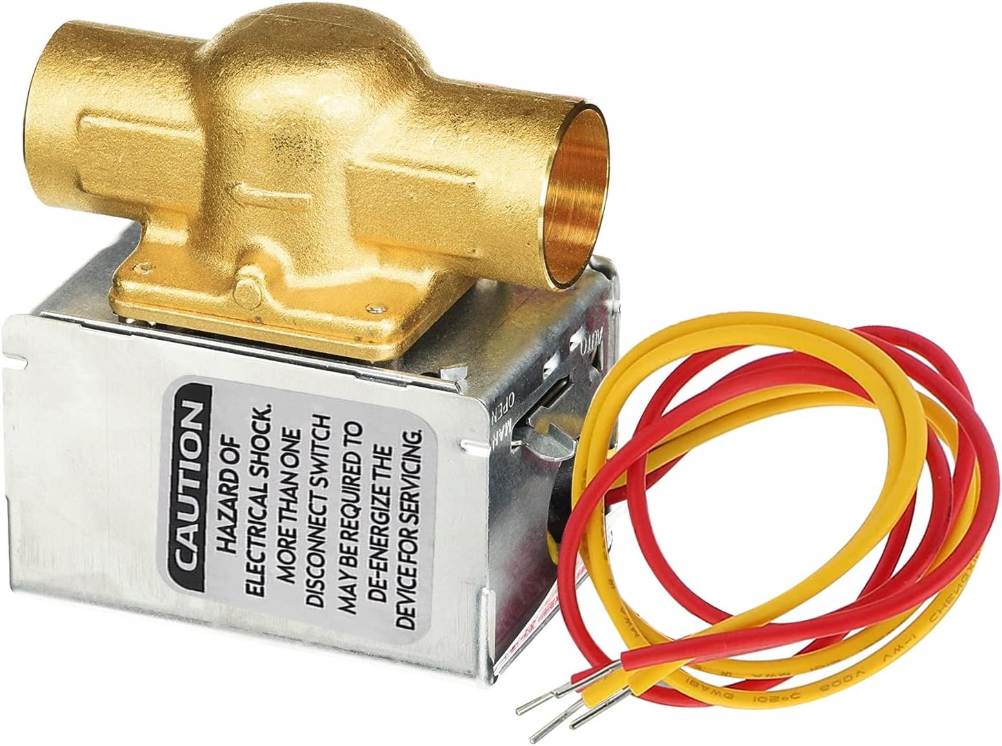
Image: The WIRELEL V8043E1012 Motorized Zone Valve, showing the brass valve body, the actuator housing, and the electrical wiring leads.
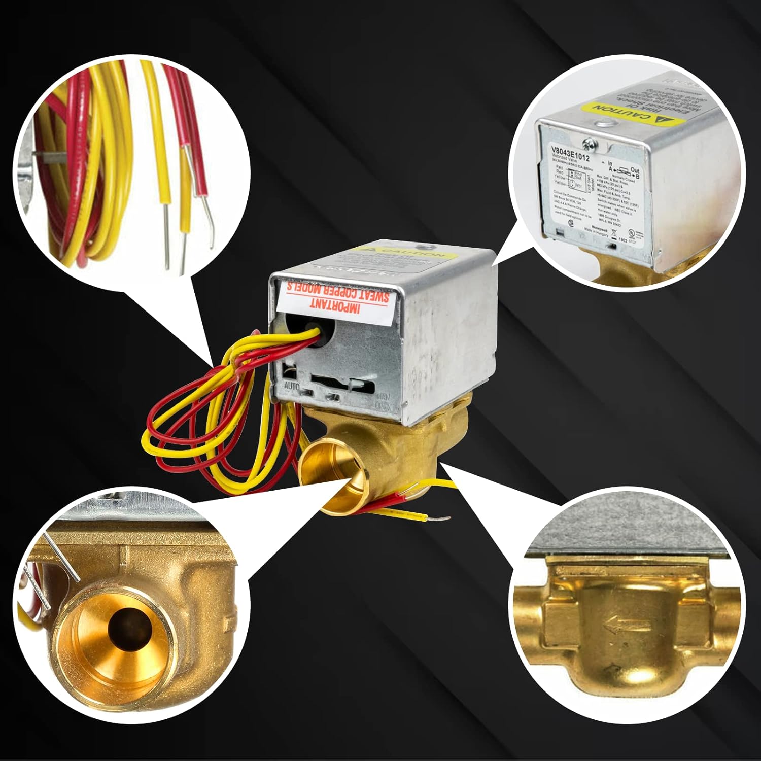
Image: A composite image showing detailed views of the valve's components, including the wiring connections, the internal mechanism, and the valve body's interior.
4. Specifications
| Feature | Specification |
|---|---|
| Model | V8043E1012 |
| Voltage | 24 VAC |
| Frequency | 50/60 Hz |
| Wiring | 2-way, 4-Wire (18" leads) |
| Connection Type | 3/4" Sweat Connection |
| Valve Body Material | Forged Brass |
| Operation | Normally Closed (NC), Spring Return to Close |
| Capacity (Cv) | 3.5 |
| Safe Working Water PSI | 20 PSI |
| Maximum Operating Temperature | 250°F (121°C) |
| Maximum Ambient Temperature | 125°F |
| End Switch | 24V |
| Electrical Connection | Screw Terminal Block |
| Product Dimensions (L x W x H) | 2.5 x 3.5 x 4 inches |
| Item Weight | 1.92 pounds |

Image: A graphic displaying key specifications of the V8043E1012 zone valve, including voltage, application, connection type, and temperature range.

Image: A diagram illustrating the physical dimensions of the V8043E1012 valve, including length, width, height, and lead wire length.
5. Setup and Installation
The V8043E1012 zone valve is designed for straightforward installation. It can often be installed or replaced without disassembling the entire valve or draining the system, especially when replacing only the actuator head.
Installation Steps:
- Step 1: Power Off. Turn off the power to the heating system at the main breaker or fuse box to ensure safety.
- Step 2: Locate and Remove Old Valve (if applicable). If replacing an existing valve, identify its location. Use a screwdriver to remove any mounting screws and carefully detach the old valve or actuator head.
- Step 3: Prepare Connections. Ensure the pipe connections are clean and ready for the 3/4" sweat connection. If replacing only the actuator, ensure the valve body is clean and free of debris.
- Step 4: Connect Wiring. Connect the two thermostat wires and the two pipe connections correctly. Refer to the wiring diagram on the valve's label for precise connections. The valve has 18-inch leads for easy connection to a 24V thermostat.
- Step 5: Mount the Valve. Secure the new V8043E1012 valve in place using the provided mounting screws. Ensure it is firmly attached and aligned correctly with the piping.
- Step 6: Test System. After installation, conduct a comprehensive test of your heating system to confirm the correct operation of the V8043E1012 Valve. Check for any leaks at the sweat connections.
- Step 7: Restore Power. Once testing is complete and no issues are found, restore power to the heating system.
Note: The actuator motor can be replaced without removing the valve body or draining the system. Similarly, the power head can be replaced without damaging plumbing line connections or draining the system.

Image: A close-up of the valve's label, showing the model number, electrical specifications, and a basic wiring diagram for connection.
6. Operating Instructions
The V8043E1012 Motorized Zone Valve operates automatically in response to a 24V thermostat signal.
Automatic Operation:
- When the thermostat calls for heat, it sends a 24V signal to the valve.
- The valve's motor will open the valve, allowing hot water to flow into the designated heating zone.
- The end switch provides feedback to the boiler or circulating pump, indicating that the valve is open and heat is required.
- When the thermostat is satisfied, the 24V signal is removed.
- The valve, being Normally Closed (NC) with a spring return, will automatically close, stopping the flow of hot water to that zone.
Manual Operation:
In case of a power failure or for system draining, the valve can be operated manually:
- Locate the manual opener lever on the valve actuator.
- Move the lever to the "OPEN" position to manually open the valve.
- Once power is restored, or manual operation is no longer needed, the valve will return to automatic operation.
7. Maintenance
The WIRELEL V8043E1012 Motorized Zone Valve is designed for minimal maintenance. Regular checks can help ensure its longevity and proper function.
- Annual Inspection: Periodically inspect the valve for any signs of leaks, corrosion, or physical damage.
- Wiring Check: Ensure all electrical connections are secure and free from corrosion.
- Actuator Function: Observe the valve's operation during a heating cycle to confirm it opens and closes smoothly.
- Cleaning: Keep the exterior of the valve clean and free from dust or debris. Do not use harsh chemicals.
If any issues are observed, refer to the Troubleshooting section or contact customer support.
8. Troubleshooting
This section addresses common issues you might encounter with your V8043E1012 Motorized Zone Valve.
| Problem | Possible Cause | Solution |
|---|---|---|
| Valve does not open when thermostat calls for heat. |
|
|
| Valve does not close when thermostat is satisfied. |
|
|
| Water leakage from valve. |
|
|
| Heating system not responding correctly. |
|
|
For issues not listed here, or if troubleshooting steps do not resolve the problem, contact customer support.
9. Warranty and Support
For warranty information or technical assistance, please contact WIRELEL customer support through the retailer where the product was purchased or visit the official WIRELEL website.
Please have your product model number (V8043E1012) and purchase date available when contacting support.