1. Introduction
The ArecaIoT CWT-MB307D-E-485 is a versatile Modbus IO acquisition module designed for industrial automation applications. It features 8 analog inputs (AI), 8 digital inputs (DI), and 8 digital outputs (DO), supporting both RS485 and Ethernet communication interfaces. This module is engineered for reliable data acquisition and control, offering robust performance in various industrial environments.

Figure 1: Front view of the CWT-MB307D-E-485 Modbus IO Acquisition Module, displaying its various input and output terminals, communication ports, and status indicators.

Figure 2: Application diagram showing the CWT Modbus IO Module integrating with SCADA systems, PLCs, and various industrial sensors and actuators for digital input, digital output, analog input, and analog output functions.
2. Key Features
- Digital Input (DI): 8 channels, 5-30VDC input, optocoupler isolation, 2500V lightning protection, overvoltage, overcurrent protection, 0.01s sample rate.
- Digital Output (DO): 8 channels, relay output, 5A/250VAC, 5A/30VDC load, response time ≤ 0.01s.
- Analog Input (AI): 8 channels, 4-20mA (option: 0-20mA/0-5V/1-5V/0-10V) input, precision: 0.1%, 16 bit, 0.01s refresh rate.
- Communication Ports: RS485, Ethernet.
- Communication Protocols: Modbus RTU, Modbus TCP.
3. Specifications
| Feature | Specification |
|---|---|
| Model Number | MB307D-E-485 |
| Digital Inputs | 8 channels, 5-30VDC, Optocoupler isolated |
| Digital Outputs | 8 channels, Relay, 5A/250VAC, 5A/30VDC |
| Analog Inputs | 8 channels, 4-20mA (optional 0-20mA/0-5V/1-5V/0-10V) |
| AI Precision | 0.1%, 16-bit |
| Communication Interfaces | RS485, Ethernet |
| Protocols | Modbus RTU, Modbus TCP |
| Manufacturer | ComWinTop |
| Country of Origin | China |
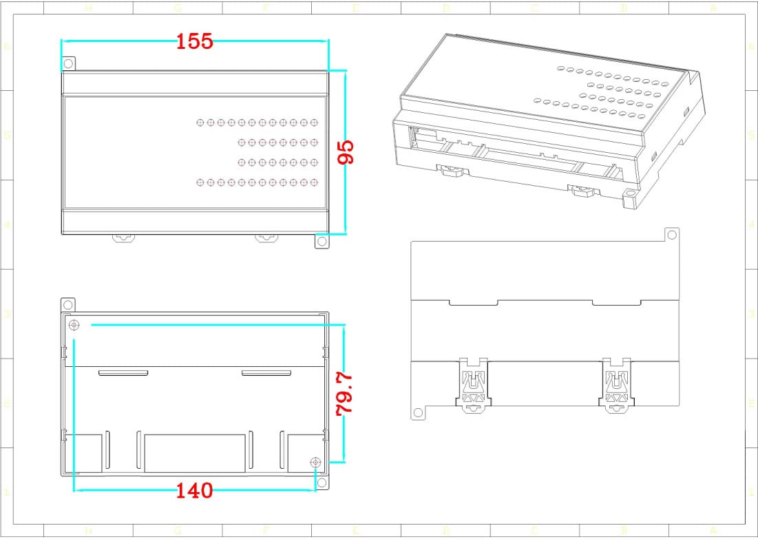
Figure 3: Dimensional drawing of the CWT-MB307D-E-485 module, showing measurements in millimeters for length, width, and height.
4. Setup and Wiring
Proper wiring is crucial for the safe and reliable operation of the CWT-MB307D-E-485 module. Ensure all connections are secure and follow local electrical codes.
4.1 Power Supply Connection
Connect a 7-30VDC power supply to the designated terminals. Observe polarity: '+' to positive, '-' to negative.
4.2 Communication Connections
- RS485: Connect the A+ and B- terminals to your RS485 network. Ensure proper termination if required by your network topology.
- Ethernet: Connect a standard RJ45 Ethernet cable to the Ethernet port for Modbus TCP communication.
4.3 Input/Output Wiring
- Analog Inputs (AI): Connect your analog sensors (e.g., 4-20mA, 0-10V) to the AI terminals (0-7). Refer to the wiring diagram for specific connections based on your sensor type.
- Digital Inputs (DI): Connect digital signals (5-30VDC) to the DI terminals (0-7).
- Digital Outputs (DO): Connect loads (up to 5A/250VAC or 5A/30VDC) to the DO relay terminals (0-7).
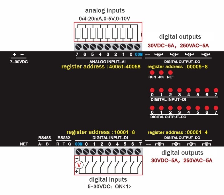
Figure 4: Detailed wiring diagram for the CWT-MB307D-E-485 module, illustrating connections for analog inputs (0/4-20mA, 0-5V, 0-10V), digital outputs (30VDC-5A, 250VAC-5A), and digital inputs (5-30VDC). Corresponding Modbus register addresses are also indicated.
5. Operating Instructions
The CWT-MB307D-E-485 module communicates using Modbus RTU (via RS485) and Modbus TCP (via Ethernet). Configuration and data access are performed by reading and writing to specific Modbus registers.
5.1 Modbus Register Addresses
Refer to the wiring diagram (Figure 4) for key Modbus register addresses:
- Analog Input (AI) Register Address: 40051-40058
- Digital Input (DI) Register Address: 10001-10008
- Digital Output (DO) Register Address: 00001-00008
Consult the full Modbus communication protocol documentation for detailed function codes and data formats.
5.2 Communication Settings
- RS485: Configure baud rate, data bits, stop bits, and parity to match your Modbus master device.
- Ethernet: The module will typically acquire an IP address via DHCP or can be configured with a static IP. Ensure the Modbus TCP port (default 502) is accessible.
6. Maintenance
The CWT-MB307D-E-485 module is designed for minimal maintenance. However, periodic checks can ensure optimal performance:
- Cleaning: Keep the module clean and free from dust and debris. Use a soft, dry cloth for cleaning. Do not use liquid cleaners.
- Environmental Conditions: Ensure the module operates within its specified temperature and humidity ranges. Avoid exposure to corrosive gases or excessive vibration.
- Connection Integrity: Periodically check all wiring connections for tightness and signs of corrosion or damage.
7. Troubleshooting
If you encounter issues with your CWT-MB307D-E-485 module, consider the following:
- No Power: Verify the 7-30VDC power supply is correctly connected and providing the specified voltage. Check power indicator LEDs on the module.
- Communication Failure (RS485):
- Check A+ and B- wiring polarity.
- Verify baud rate, data bits, stop bits, and parity settings match between the module and the Modbus master.
- Ensure RS485 termination resistors are correctly applied if necessary.
- Communication Failure (Ethernet):
- Check Ethernet cable connection and network activity LEDs.
- Verify IP address and subnet mask settings. Ensure no IP conflicts exist on the network.
- Confirm Modbus TCP port (default 502) is open and accessible.
- Incorrect Input Readings:
- Verify sensor wiring and power supply.
- Ensure the correct analog input type (e.g., 4-20mA, 0-10V) is selected or configured if applicable.
- Check Modbus register addresses for reading analog input data.
- Digital Output Not Activating:
- Verify load wiring and power supply to the load.
- Ensure the load current and voltage do not exceed the relay's specifications (5A/250VAC, 5A/30VDC).
- Check Modbus register addresses for writing to digital outputs.
8. Warranty Information
ArecaIoT products are typically covered by a limited manufacturer's warranty against defects in materials and workmanship. The specific warranty period and terms may vary. Please retain your proof of purchase. For detailed warranty information, refer to the documentation provided with your purchase or contact ArecaIoT customer support.
9. Technical Support
For technical assistance, troubleshooting beyond this manual, or inquiries regarding product functionality, please contact ArecaIoT customer support. When contacting support, please have your product model number (CWT-MB307D-E-485) and a detailed description of your issue ready.