1. Introduction
The ArecaIoT CWT-MB308D-E is a robust 32-channel digital input (DI) acquisition module designed for industrial applications. It features Ethernet communication with Modbus TCP protocol, enabling reliable data acquisition from various industrial sensors and devices. This module is engineered with advanced protection mechanisms, including 2500V lightning protection, optocoupler isolation, and safeguards against overvoltage and overcurrent, ensuring stable and secure operation in demanding environments.
This manual provides essential information for the proper installation, operation, and maintenance of your CWT-MB308D-E module.

Image 1.1: Front view of the CWT-MB308D-E module. This image displays the front panel of the CWT-MB308D module, showing the 32 digital input terminals, power input, Ethernet port, and status indicator LEDs.
2. Key Features
- Digital Input (DI): 32 channels, supporting 5-30VDC input.
- Isolation: Optocoupler isolation for enhanced signal integrity and protection.
- Protection: 2500V lightning protection, overvoltage, and overcurrent protection.
- Sample Rate: Fast 0.01s sample rate for responsive data acquisition.
- Communication Port: Ethernet.
- Communication Protocol: Modbus TCP.

Image 2.1: CWT-MB308D-E model identification. This image highlights the specific model CWT-MB308D-E, indicating its 32 digital inputs and Ethernet communication capability.
3. Setup and Installation
3.1 Physical Installation
The CWT-MB308D-E module is designed for DIN rail mounting, allowing for easy integration into industrial control cabinets. Ensure the module is securely fastened to the DIN rail to prevent movement or vibration.

Image 3.1: Bottom view with DIN rail clips. The bottom view of the module reveals the red DIN rail mounting clips, indicating easy installation in industrial control cabinets.
3.2 Wiring Connections
Carefully connect the power supply, digital inputs, and Ethernet communication cable as described below and illustrated in the wiring diagram.
- Power Supply: Connect a 7-30VDC power source to the designated power terminals. Observe polarity.
- Digital Inputs: Connect your 5-30VDC digital input signals to the 32 input channels. Each channel is opto-isolated for protection. Refer to the wiring diagram for specific terminal assignments and register addresses.
- Ethernet Communication: Connect a standard Ethernet cable to the RJ45 port for Modbus TCP communication.
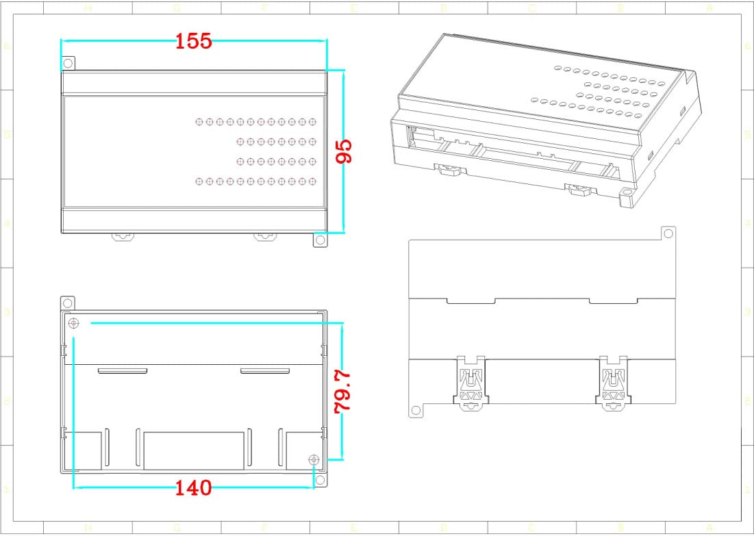
Image 3.2: Wiring diagram and Modbus register addresses. This diagram illustrates the wiring connections for the 32 digital inputs (5-30VDC) and provides corresponding Modbus register addresses for each input group.
3.3 Initial Configuration
After physical installation and wiring, the module can be configured via its Ethernet interface using Modbus TCP. The default IP address and other network parameters may need to be set according to your network environment. Consult the Modbus TCP communication protocol documentation for detailed register maps and configuration commands.
4. Operating Instructions
The CWT-MB308D-E operates as a Modbus TCP slave device, allowing a Modbus master (e.g., PLC, SCADA system, or PC software) to read the status of its 32 digital inputs.
4.1 Reading Digital Input Status
To read the status of the digital inputs, the Modbus master sends read requests to the module's assigned Modbus TCP address. The input status (ON/OFF) corresponds to the voltage level detected on each channel (5-30VDC for ON). Refer to Image 3.2 for the specific Modbus register addresses associated with each group of digital inputs.
- Input Voltage: 5-30VDC for an 'ON' state.
- Modbus Function Code: Typically, Function Code 02 (Read Input Status) or 04 (Read Input Registers) is used, depending on the specific implementation.
- Register Addresses: As indicated in Image 3.2, input groups are mapped to specific Modbus register addresses (e.g., 10001-8, 10009-16, 10017-24, 10025-32).
The module's RUN LED indicates operational status. Other LEDs (e.g., 485, 232 if present on other variants) may indicate communication activity.
5. Maintenance
The CWT-MB308D-E module is designed for reliable, low-maintenance operation in industrial environments. Regular maintenance helps ensure its longevity and performance.
- Cleaning: Periodically clean the module's exterior with a soft, dry cloth to remove dust and debris. Do not use liquid cleaners or solvents.
- Connection Checks: Routinely inspect all wiring connections (power, digital inputs, Ethernet) to ensure they are secure and free from corrosion or damage.
- Environmental Conditions: Ensure the module operates within its specified environmental conditions (temperature, humidity) to prevent premature failure.
- Firmware Updates: If firmware updates become available, follow the manufacturer's instructions carefully.
The built-in 2500V lightning protection and optocoupler isolation significantly reduce the risk of damage from electrical disturbances, contributing to the module's overall reliability and reducing maintenance needs.
6. Troubleshooting
If you encounter issues with the CWT-MB308D-E module, refer to the following troubleshooting steps:
- No Power:
- Check the 7-30VDC power supply connection and ensure it is providing the correct voltage.
- Verify power supply polarity.
- Check the power indicator LED on the module.
- No Ethernet Communication:
- Ensure the Ethernet cable is securely connected to both the module and the network device.
- Verify network settings (IP address, subnet mask, gateway) are correctly configured for the module and the Modbus master.
- Check network activity LEDs on the Ethernet port.
- Confirm the Modbus master is configured to communicate with the correct Modbus TCP port and slave ID.
- Incorrect Digital Input Readings:
- Verify the input signal voltage is within the 5-30VDC range for an 'ON' state.
- Check the wiring of the digital input sensors to the module terminals.
- Ensure the Modbus master is reading the correct register addresses for the desired input channels (refer to Image 3.2).
- Confirm the input signal is stable and not subject to excessive noise.
If problems persist after following these steps, contact ArecaIoT technical support for further assistance.
7. Specifications
| Parameter | Specification |
|---|---|
| Model | MB308D-E |
| Digital Input Channels | 32 |
| Digital Input Voltage | 5-30VDC |
| Input Isolation | Optocoupler isolation |
| Protection | 2500V Lightning Protection, Overvoltage, Overcurrent Protection |
| Sample Rate | 0.01s |
| Communication Port | Ethernet |
| Communication Protocol | Modbus TCP |
| Power Supply | 7-30VDC |
| Manufacturer | ComWinTop |
| ASIN | B0BS6BSFBB |
| Country of Origin | China |
7.1 Dimensions
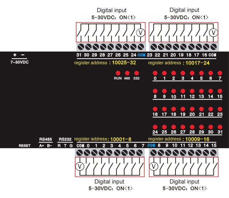
Image 7.1: Module dimensions. This technical drawing provides the physical dimensions of the CWT-MB308D module, including length, width, and height, essential for installation planning.
7.2 CWT-MB Series Overview
The CWT-MB308D-E is part of the CWT Modbus IO module series, which offers a range of multi-channel DI/DO/AI/PT100 input/output configurations. These modules are widely used in various industrial sectors for cost-effective, reliable data acquisition and control.

Image 7.2: CWT-MB series Modbus IO Module variants. This table lists various models within the CWT-MB series, detailing their input/output configurations such as Digital Input (DI), Digital Output (DO), Analog Input (AI), and Analog Output (AO).
8. Warranty and Support
Specific warranty details for the ArecaIoT CWT-MB308D-E module are not provided in the available product information. For warranty claims, technical support, or any product-related inquiries, please contact the manufacturer, ComWinTop, or your authorized distributor.
Please retain your proof of purchase for any warranty-related services.