Walfront AUA800U
AUA800U Optical Time Domain Reflectometer
User Manual
Model: AUA800U
Brand: Walfront
1. Introduction
The Walfront AUA800U Optical Time Domain Reflectometer (OTDR) is a versatile and powerful instrument designed for the evaluation of FTTx and access network construction and maintenance. It integrates multiple functions including OTDR, Stable Light Source (LS), Optical Power Meter (OPM), Visual Fault Locator (VFL), and RJ45 cable testing capabilities. With its 4.3-inch touchable color display, it provides an intuitive interface for identifying fiber breaks, measuring optical cable lengths, and calculating relative optical power loss, ensuring efficient and accurate fiber optic network diagnostics.
2. Safety Information
Please read all safety warnings and instructions carefully before using the AUA800U OTDR. Failure to follow these instructions may result in injury or damage to the device.
- Laser Safety: This device contains a laser light source. Do not stare directly into the optical output port or view with optical instruments. Invisible laser radiation may be emitted.
- Battery Safety: Use only the specified charging cable and plug. Do not disassemble, crush, or expose the built-in Li-battery to extreme temperatures or fire.
- Environmental Conditions: Operate the device within the specified temperature and humidity ranges. Avoid exposure to dust, moisture, or corrosive substances.
- Handling: Handle the device with care. Avoid dropping or subjecting it to strong impacts.
- Maintenance: Refer to the maintenance section for cleaning and care instructions. Do not attempt to service the device yourself.
3. Package Contents
Verify that all items listed below are included in your package. If any items are missing or damaged, please contact your supplier.
- 1 x Optical Time Domain Reflectometer (AUA800U)
- 1 x Instruction Manual
- 1 x Charging Cable
- 1 x Power Plug
- 1 x SC Adapter
- 1 x RJ45 Receiver
- 1 x Storage Bag
- 1 x Strap
- 1 x FC to LC Adapter
- 1 x Memory Card (pre-installed)

Figure 3.1: AUA800U OTDR with its complete set of accessories, including the main unit, storage bag, RJ45 receiver, charging cable, plug, and various adapters.
4. Product Overview and Interfaces
Familiarize yourself with the main components and interfaces of the AUA800U OTDR.
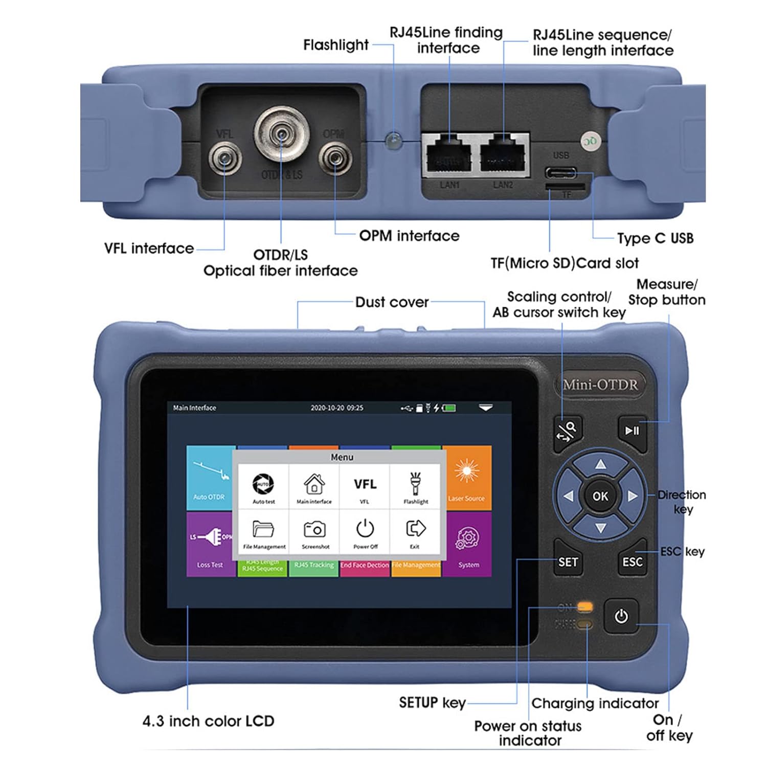
Figure 4.1: Detailed diagram of the AUA800U OTDR's interfaces and controls. Key features include the 4.3-inch color LCD, VFL interface, OTDR/LS optical fiber interface, OPM interface, RJ45 interfaces (LAN1, LAN2), USB port, TF (Micro SD) card slot, and various control buttons (OK, SET, ESC, Direction keys, Power).

Figure 4.2: Close-up view of the optical interfaces on the AUA800U OTDR. These include the VFL Red Light Source Interface (1), OTDR/Stable Light Source Interface (2), OPM Optical Power Meter Interface (3), and an LED lamp Flashlight (4). Various adapters like FC and SC are shown for compatibility.
4.1 Physical Dimensions
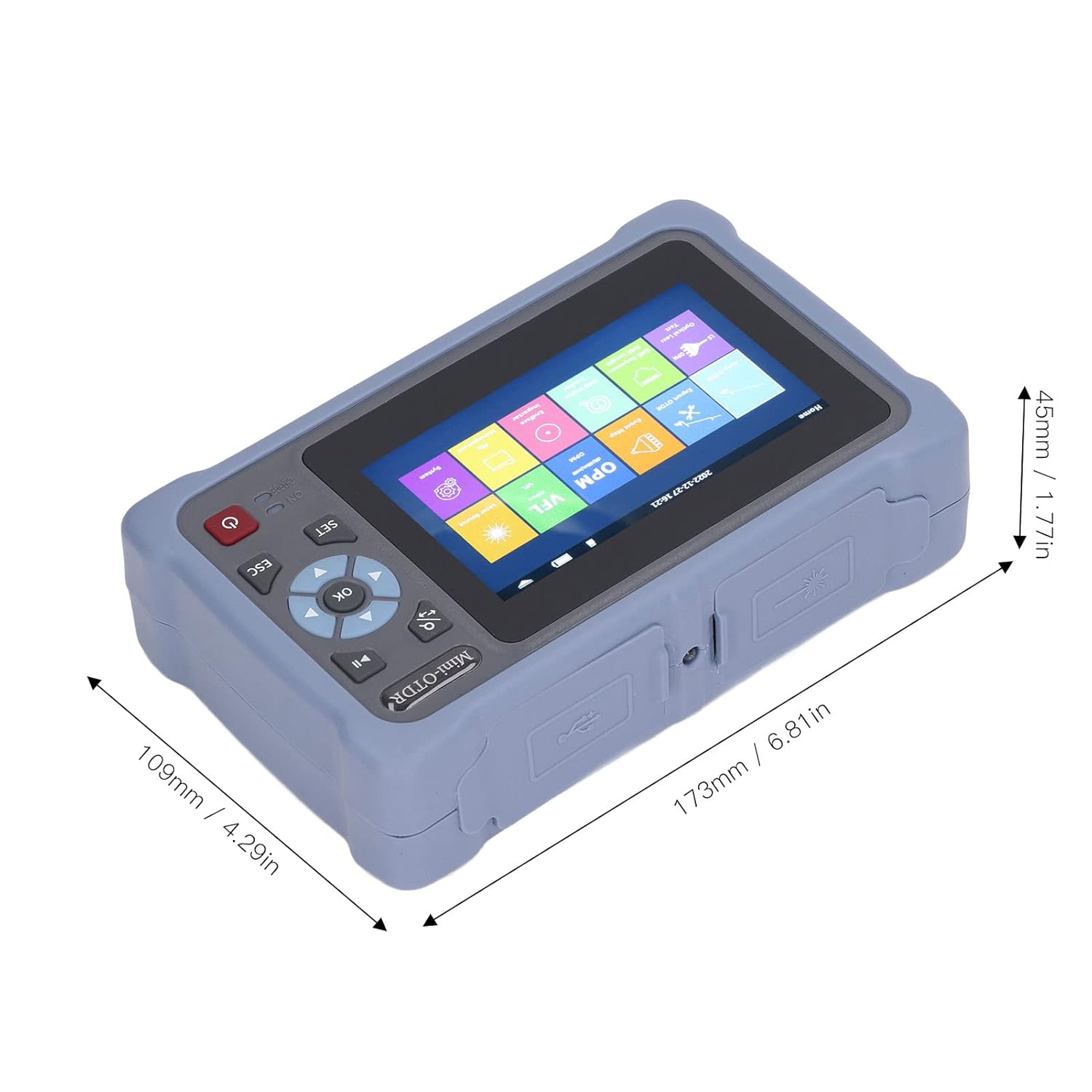
Figure 4.3: Dimensions of the AUA800U OTDR unit, showing approximate measurements of 173mm (6.81in) in length, 109mm (4.29in) in width, and 45mm (1.77in) in height.
5. Setup
5.1 Charging the Device
The AUA800U OTDR has a built-in 3.7V, 4000mAh Li-battery. Before first use, ensure the device is fully charged.
- Connect the charging cable to the Type-C USB port on the device.
- Connect the other end of the charging cable to the provided power plug and plug it into a standard electrical outlet.
- The charging indicator light will illuminate during charging. It will change or turn off once charging is complete.
5.2 Installing Batteries for RJ45 Receiver
The RJ45 Receiver requires 2 x AAA batteries (not included).
- Open the battery compartment on the RJ45 Receiver.
- Insert 2 AAA batteries, ensuring correct polarity (+/-).
- Close the battery compartment securely.
5.3 Powering On/Off
Press and hold the power button (usually located near the bottom right of the screen) for a few seconds to turn the device on or off.
6. Operating Instructions
The AUA800U OTDR features a 4.3-inch touchable color display for easy navigation and operation. The main interface provides access to various functions.
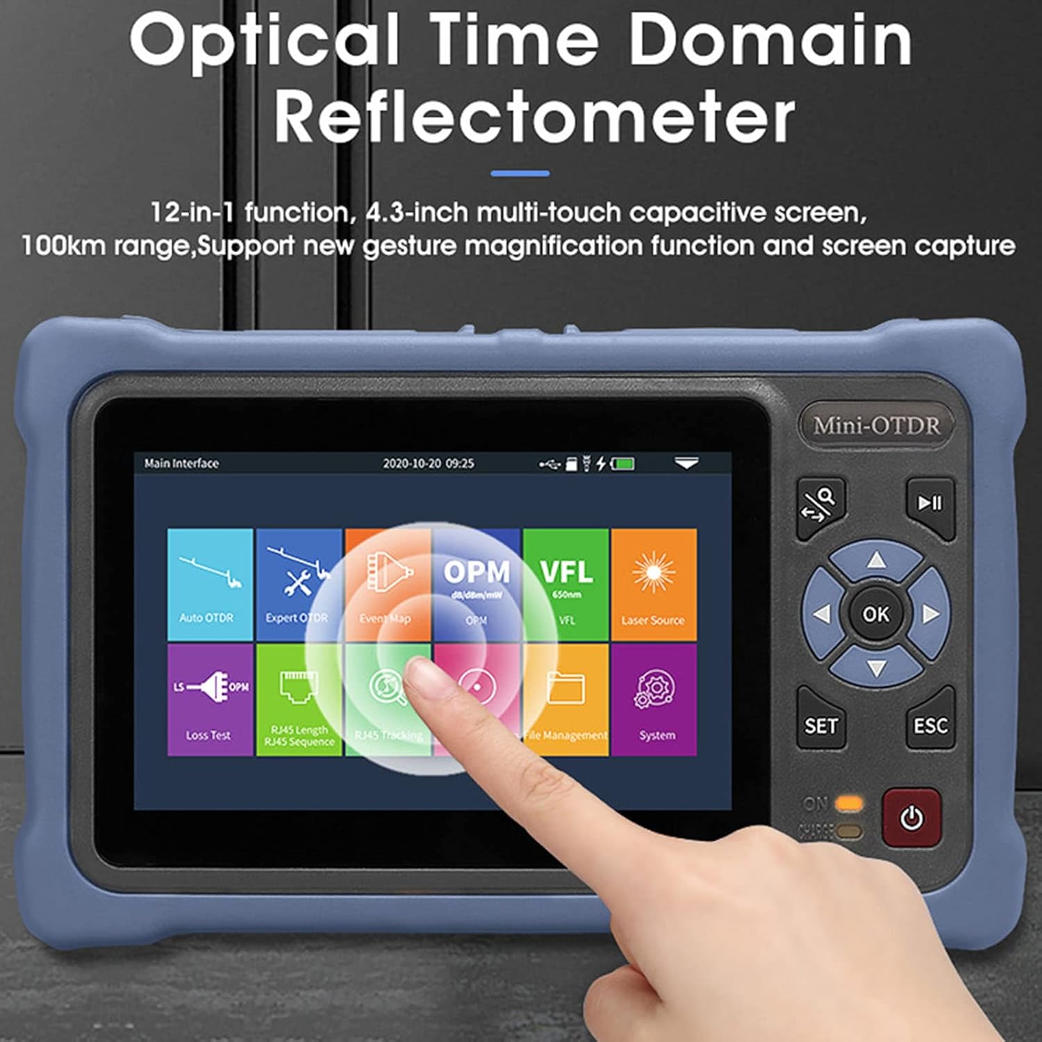
Figure 6.1: The main interface of the AUA800U OTDR, displaying icons for various functions such as Auto OTDR, Expert OTDR, Event Map, OPM, VFL, Laser Source, Loss Test, RJ45 Length, RJ45 Sequence, RJ45 Tracking, End Face Detection, File Management, and System settings.
6.1 OTDR Functions (Auto OTDR, Expert OTDR, Event Map)
The OTDR function is crucial for fiber optic cable testing, identifying breaks, and measuring lengths.

Figure 6.2: Screenshots illustrating the interfaces for Auto OTDR, Expert OTDR, Event Map, and OPM functions. These show graphical representations of fiber attenuation, event lists, and power measurements.
6.1.1 Auto OTDR
This mode simplifies testing by automatically setting parameters.
- From the main menu, select 'Auto OTDR'.
- Just set the wavelength and measurement time. Other parameters are automatically selected by the instrument.
- Press 'AutoTest' to begin the test.

Figure 6.3: The Auto OTDR test function screen, showing the graph of the fiber optic cable, settings, zoom, cursor A, and file options. The user only needs to set wavelength and measurement time.
6.1.2 Expert OTDR
For advanced users, this mode allows manual configuration of test parameters.
- Select 'Expert OTDR' from the main menu.
- Manually set parameters such as wavelength, test range, and pulse width.
- Press 'AutoTest' to start the test.
6.1.3 Event Map
The Event Map function provides a graphical representation of events along the fiber.
- Select 'Event Map' from the main menu.
- The function automatically tests and displays information such as total length, total loss, slope, and the number of events.
- Fusion points and breakpoints are graphically displayed for easy identification.
6.2 VFL (Visual Fault Locator)
The VFL function emits a visible red laser light to quickly locate breaks, bends, or poor connections in fiber optic cables over short distances.
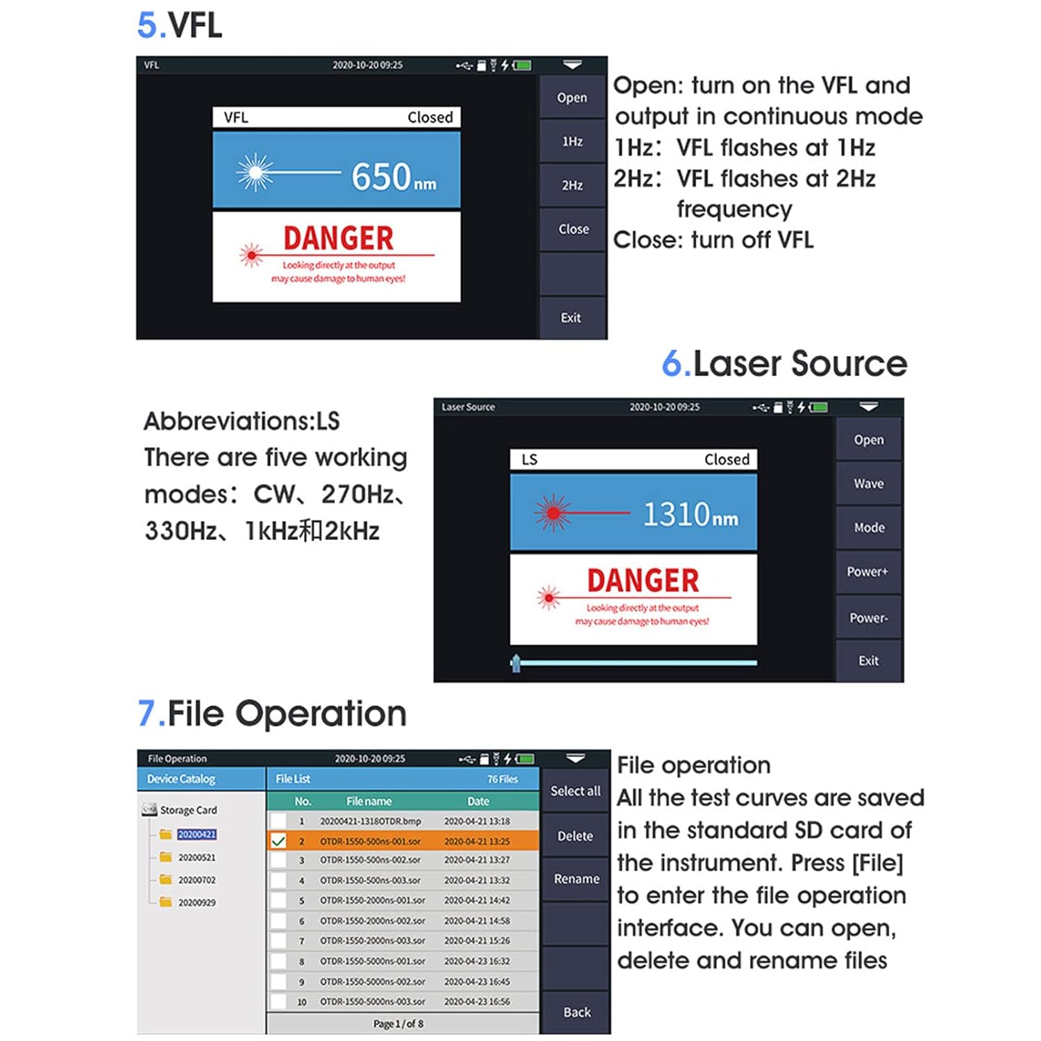
Figure 6.4: Screenshots showing the VFL, Laser Source, and File Operation interfaces. The VFL screen indicates open/closed status and frequency options (1Hz, 2Hz). The Laser Source screen shows wavelength and operating modes. The File Operation screen displays saved test files.
- Select 'VFL' from the main menu.
- Connect the fiber to the VFL Red Light Source Interface (2.5mm universal SC, FC, ST).
- Choose 'Open' to turn on the VFL. You can select 1Hz (flashes at 1Hz) or 2Hz (flashes at 2Hz) modes.
- Select 'Close' to turn off the VFL.
6.3 Laser Source (Stable Light Source)
The stable light source function provides a continuous optical signal for loss measurement.
- Select 'Laser Source' from the main menu.
- Connect the fiber to the OTDR or Stable Light Source Interface.
- Choose 'Open' to activate the laser source.
- Select the desired wavelength (e.g., 1310nm, 1550nm) and operating mode (CW, 270Hz, 330Hz, 1KHz, 2KHz).
- Select 'Close' to turn off the laser source.
6.4 OPM (Optical Power Meter)
The OPM function measures the optical power of a fiber optic signal.
- Select 'OPM' from the main menu.
- Connect the fiber to the OPM Optical Power Meter Interface (2.5mm universal SC, FC, ST).
- The device will display the measured optical power in dBm.
- You can adjust the wavelength and set reference values if needed.
6.5 RJ45 Cable Testing Functions
The AUA800U OTDR includes functions for testing RJ45 network cables.

Figure 6.5: The RJ45 cable testing interface, showing options for line seeking (tracking), line sequence measurement, and line length measurement. The remote RJ45 unit is also depicted.
6.5.1 RJ45 Line Seeking/Tracking
- Connect one end of the RJ45 cable to the LAN1 or LAN2 port on the OTDR.
- Use the RJ45 Receiver to trace the cable and locate it.
6.5.2 RJ45 Line Sequence Measurement
- Connect the RJ45 cable to the LAN1 or LAN2 port and the remote RJ45 unit.
- The screen will display the wiring sequence (e.g., T568A, T568B) and identify any miswires or open circuits.
6.5.3 RJ45 Line Length Measurement
- Connect the RJ45 cable to the LAN1 or LAN2 port and the remote RJ45 unit.
- The device will measure and display the length of the RJ45 cable.
6.6 File Operations
The AUA800U OTDR allows you to save, open, delete, and rename test files.
- Select 'File Management' from the main menu.
- All test curves are saved on the pre-installed memory card.
- You can browse the list of saved files, select them, and perform operations like 'Open', 'Delete', or 'Rename'.
7. Maintenance
Proper maintenance ensures the longevity and accuracy of your AUA800U OTDR.
- Cleaning: Use a soft, dry, lint-free cloth to clean the device's exterior. For the screen, use a screen-specific cleaning solution if necessary.
- Optical Ports: Keep all optical ports clean and free of dust. Use specialized fiber optic cleaning tools (e.g., fiber optic cleaning pens or wipes) to clean the connector interfaces before each use. Dust and debris can significantly affect measurement accuracy.
- Storage: When not in use, store the device in its provided storage bag in a cool, dry place, away from direct sunlight and extreme temperatures.
- Battery Care: If storing for an extended period, ensure the battery is partially charged (around 50%) to prolong its lifespan. Recharge periodically if stored for very long durations.
- Avoid Impact: Protect the device from drops and strong vibrations.
8. Troubleshooting
This section addresses common issues you might encounter with the AUA800U OTDR.
| Problem | Possible Cause | Solution |
|---|---|---|
| Device does not power on. | Low battery; Power button not pressed long enough; Device malfunction. | Charge the device fully. Press and hold the power button for at least 3-5 seconds. If issue persists, contact support. |
| Inaccurate OTDR/OPM readings. | Dirty optical connectors; Incorrect test parameters; Damaged fiber. | Clean all optical connectors thoroughly. Verify test parameters (wavelength, range, pulse width). Inspect fiber for damage. |
| VFL light is dim or not visible. | Dirty VFL port; Fiber not properly connected; VFL turned off. | Clean the VFL port. Ensure fiber is securely connected. Turn on VFL from the menu. |
| RJ45 test fails or is inaccurate. | RJ45 receiver batteries low/dead; Cable not properly connected; Faulty RJ45 cable. | Replace AAA batteries in the RJ45 receiver. Ensure both ends of the cable are securely connected. Test with a known good cable. |
| Screen is unresponsive. | Software glitch; Extreme temperature. | Restart the device. Ensure operating within specified temperature range. |
9. Specifications
Detailed technical specifications for the AUA800U Optical Time Domain Reflectometer.
| Feature | Specification |
|---|---|
| Item Type | Optical Time Domain Reflectometer |
| Model | AUA800U |
| Material | ABS |
| Connector Model | UPC |
| Test Wavelength | 1310nm, 1550nm |
| Test Range | 5m - 100km |
| Dynamic Range | 26dB, 24dB |
| Display | 4.3 inch touchable color display |
| Power Supply (Main Unit) | Built-in 3.7V, 4000mAh Li-battery |
| Power Supply (RJ45 Receiver) | 2 x AAA batteries (not included) |
| VFL Red Light Source Interface | 2.5mm universal (SC, FC, ST) |
| OTDR / Stable Light Source Interface | Changeable (SC, UPC, FC, UPC) |
| OPM Optical Power Meter Interface | 2.5mm universal (SC, FC, ST) |
| Package Dimensions | 8.66 x 5.12 x 3.94 inches |
| Item Model Number | WALFRONTnosqd9v84e |
| Manufacturer | WALFRONT |
| Country of Origin | China |
10. Warranty and Support
For warranty information and technical support, please refer to the documentation provided with your purchase or contact Walfront customer service through their official channels. Keep your purchase receipt as proof of purchase for warranty claims.
For further assistance, you may visit the Walfront Store on Amazon: Walfront Amazon Store
Ask a question about this manual
Ask about setup, troubleshooting, compatibility, parts, safety, or missing instructions. Manuals+ will review the question and use this page’s manual context to help answer it.