Wemay WemayE16640
User Manual for ERYUE DSO2512G Oscilloscope
Model: WemayE16640
1. Introduction
This manual provides detailed instructions for the operation, maintenance, and troubleshooting of the ERYUE DSO2512G Portable Handheld Dual Channel Oscilloscope. Please read this manual thoroughly before using the device to ensure proper and safe operation.
2. Product Overview
The ERYUE DSO2512G is a portable handheld dual-channel oscilloscope featuring a 120M bandwidth and a 2.8-inch display. It integrates ARM and FPGA chip collocation for high-speed signal acquisition and data processing. This device also includes a signal generator capable of outputting various waveforms.

Figure 2.1: Front view of the DSO2512G Oscilloscope. The device features a central display screen showing waveform data, surrounded by control buttons for navigation, menu access, and function selection.
3. Key Features
- Bandwidth: 120M (single channel), 60M (dual channel).
- Sampling Rate: 500M.
- Display: 2.8-inch screen.
- Vertical Sensitivity: 10mV/div to 10V/div.
- Time Base: 5ns to 10s.
- Processor: ARM and FPGA chip collocation for high-speed processing.
- Signal Generator: Outputs 2.5V amplitude waveforms (Sine: 0-10MHz, Others: 0-2MHz).
- Measurement Options: Frequency, Peak-to-Peak, Duty cycle, Amplitude, RMS, Average, Period, +Pulse width, -Pulse width, Max, Min, Top, Base, -Duty cycle.
- FFT: Supports logarithmic, linear, and music spectrum display modes.
- Waveform Save/View: Ability to save and view up to 250 waveforms.
- XY Mode: Supported for phase relationship analysis.
- Trigger Type: Rise/Fall.
- Max Voltage: ±40V (x1), ±400V (x10).
- Battery: 4000mAh lithium battery.
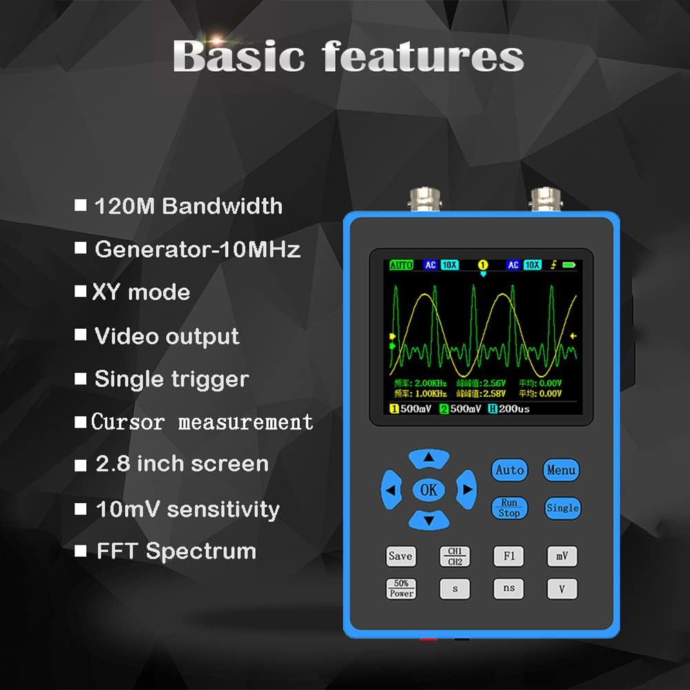
Figure 3.1: Visual summary of the oscilloscope's basic features, highlighting its technical capabilities and display characteristics.

Figure 3.2: High Bandwidth capability. The 120M bandwidth allows for versatile measurement tests in applications such as MCU debugging, car repair, and home appliance maintenance.

Figure 3.3: High-Performance Processor. The device utilizes a combination of ARM and FPGA chips for efficient signal sampling and data processing.

Figure 3.4: Signal Generator Function. The oscilloscope can output various waveforms with 2.5V amplitude, including sine, square, triangle, half, and singh waves. The sine wave frequency range is 0-10MHz, and others are 0-2MHz.

Figure 3.5: FFT Spectrum Analysis. The device supports FFT (Fast Fourier Transform) for converting time domain waveforms into frequency domain, with logarithmic, linear, and music spectrum display options.

Figure 3.6: Waveform Save and View. Users can save screen waveforms and view up to 250 stored waveforms, with the option to delete unwanted ones.
4. What's in the Box
Upon opening the package, please verify that all components are present and undamaged:
- 1 x ERYUE DSO2512G Oscilloscope
- 2 x Probes
- 1 x Video Cable
- 1 x Gan Cable
- 1 x Storage Bag
- 1 x User Manual (this document)
5. Setup
5.1 Charging the Battery
The oscilloscope is powered by a built-in 4000mAh lithium battery. Before first use, ensure the device is fully charged. Connect the provided charging cable to the device's charging port and a suitable USB power adapter (not included). The charging indicator will show the charging status.
5.2 Attaching Probes
Connect the oscilloscope probes to the BNC connectors on the top of the device. Ensure a secure connection by twisting the probe connector until it locks into place. The device supports two channels.
5.3 Initial Power On
Press and hold the power button (location typically on the side or front panel) until the display illuminates. The device will perform a self-test and then display the main measurement interface.
6. Operating Instructions
6.1 Basic Measurement
- Power On: Turn on the oscilloscope as described in Section 5.3.
- Connect Probe: Attach a probe to the desired channel (CH1 or CH2).
- Connect to Circuit: Connect the probe tip to the test point in your circuit and the ground clip to the circuit's ground.
- Auto-Set: Press the "Auto" button to automatically adjust vertical and horizontal settings for a stable waveform display.
- Adjust Settings: Use the navigation buttons and "Menu" button to fine-tune vertical sensitivity (V/div), time base (s/div), and trigger settings as needed.
- Read Measurements: The display will show real-time waveform data and automatic measurements (e.g., Frequency, P-eak to P-eak).

Figure 6.1: Examples of waveform displays on the oscilloscope, demonstrating its ability to capture and analyze different signal types, including sine waves and Lissajous figures in XY mode.
6.2 Signal Generator Function
The oscilloscope can also function as a signal generator. The output port for the signal generator is typically located at the bottom of the device (red hole for signal, black hole for GND).
- Access Generator: Navigate to the signal generator function through the menu.
- Select Waveform: Choose the desired waveform type (sine, square, triangle, etc.).
- Set Frequency: Adjust the output frequency. Sine waves support 0-10MHz, others 0-2MHz.
- Connect Output: Connect the signal generator output to your target circuit.
6.3 FFT Spectrum Analysis
The FFT (Fast Fourier Transform) function allows for frequency domain analysis of signals.
- Enter FFT Mode: Select FFT from the main menu.
- Choose Display Mode: Select between logarithmic, linear, or music spectrum display modes based on your analysis needs.
- Analyze Spectrum: Observe the frequency components of your input signal.
6.4 Waveform Saving and Viewing
To save a waveform displayed on the screen:
- Save Waveform: Press the "Save" button (or navigate via menu) to capture the current waveform.
- View Saved Waveforms: Access the waveform preview page to browse saved waveforms. Up to 250 waveforms can be stored.
- Delete Waveforms: Unwanted waveforms can be deleted from the storage.
7. Maintenance
- Cleaning: Use a soft, dry cloth to clean the device. Do not use abrasive cleaners or solvents.
- Storage: Store the oscilloscope in a cool, dry place, away from direct sunlight and extreme temperatures. Use the provided storage bag for protection.
- Battery Care: For long-term storage, charge the battery to approximately 50% every three months to prolong its lifespan.
- Probe Care: Handle probes carefully. Avoid bending or damaging the probe tips and cables.
8. Troubleshooting
| Problem | Possible Cause | Solution |
|---|---|---|
| Device does not power on. | Battery is depleted. | Charge the device using the provided cable. |
| No waveform displayed. | Probe not connected correctly; Signal too small or too large; Incorrect trigger settings. | Ensure probes are securely connected. Use "Auto" button. Adjust vertical sensitivity (V/div) and trigger level. Check probe compensation. |
| Unstable waveform. | Incorrect trigger source or level; Noise in signal. | Adjust trigger level and source. Ensure proper grounding. |
| Display is frozen. | Software glitch. | Perform a soft reset by holding the power button until the device turns off, then restart. |
9. Specifications
| Parameter | Value |
|---|---|
| Brand | Wemay |
| Model Number | WemayE16640 |
| Channels | 2 |
| Bandwidth | 120M (single channel), 60M (dual channel) |
| Sampling Rate | 500M |
| Rise Time | <3ns |
| Storage Depth | 128Kbit |
| Impedance | 1MΩ |
| Vertical Sensitivity | 10mV/div~10V/div |
| Time Base | 5ns~10s |
| Max Voltage | ±40V (x1), ±400V (x10) |
| Battery | 4000mAh Lithium |
| Product Dimensions | 8.27 x 5.51 x 4.53 inches |
| Material | ABS (device body), Lithium (battery) |
10. Warranty and Support
For warranty information and technical support, please refer to the contact details provided with your purchase or visit the official Wemay website. Keep your purchase receipt as proof of purchase for warranty claims.
Return Policy: This product is subject to a 30-day refund/replacement return policy from the date of purchase.
Ask a question about this manual
Ask about setup, troubleshooting, compatibility, parts, safety, or missing instructions. Manuals+ will review the question and use this page’s manual context to help answer it.