1. Introduction and Safety Information
This manual provides essential instructions for the safe and efficient use of the Generic Nidec 12V DC Brushless Motor, model 48F704M170. Please read this manual thoroughly before installation and operation to ensure proper function and to prevent damage or injury.
Important Safety Precautions:
- Polarity Warning: Exercise extreme caution when connecting the power source. Reversing the positive and negative terminals will damage the motor. Always verify connections before applying power.
- Power Supply: Use a stable 12V DC power supply capable of providing at least 2.5 Amps.
- Installation: Ensure the motor is securely mounted in a well-ventilated area. Avoid environments with excessive dust, moisture, or corrosive substances.
- Handling: Do not apply excessive force to the motor shaft or housing.
- Modifications: Do not attempt to disassemble or modify the motor. Unauthorized modifications will void the warranty and may lead to malfunction or injury.
- Intended Use: This motor is primarily designed for fan applications. Using it for unintended purposes may result in damage or reduced performance.
2. Product Overview
The Generic Nidec 48F704M170 is a 12V DC brushless external rotor motor, designed for applications requiring efficient and reliable rotational power, such as DC fans. It features a variable frequency design and integrates a Hall sensor for precise control. This motor operates at approximately 1100 RPM and draws 2.5 Amps under normal load.
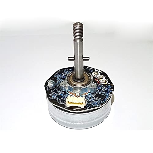
Figure 2.1: Front view of the Generic Nidec 12V DC Brushless Motor 48F704M170. This image shows the main body and shaft of the motor.
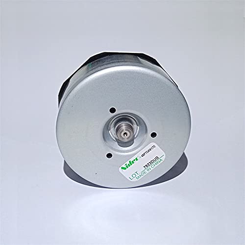
Figure 2.2: Rear view of the Nidec 48F704M170 motor, showing the back casing and a product label with model information.
3. Setup and Installation
Proper setup is crucial for the motor's performance and longevity. Follow these steps carefully:
3.1 Mounting the Motor
The motor can be mounted using appropriate fasteners through the designated mounting holes. Ensure the mounting surface is stable and capable of supporting the motor's weight and operational forces. Refer to the dimensions for proper fitment.
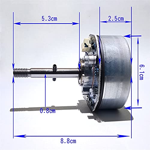
Figure 3.1: Dimensional drawing of the Nidec 48F704M170 motor, showing key measurements in centimeters for installation planning. The total length is 8.8 cm, shaft length 5.3 cm, shaft diameter 0.8 cm, and motor body diameter 6.1 cm with a thickness of 2.5 cm.
3.2 Electrical Connections
This brushless DC motor requires a compatible motor controller (not included) for operation. The motor features a multi-pin connector for power and control signals. Refer to the pinout diagram below for correct wiring.
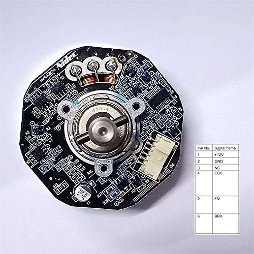
Figure 3.2: View of the motor's circuit board with a detailed pinout table. The table indicates the following connections: Pin 1: +12V (Power), Pin 2: GND (Ground), Pin 3: NC (No Connection), Pin 4: CLK (Clock/Speed Signal), Pin 5: FG (Frequency Generator/Tachometer Output), Pin 6: BRK (Brake).
Wiring Guide:
- Connect Pin 1 (+12V) to the positive terminal of your 12V DC power supply.
- Connect Pin 2 (GND) to the negative terminal of your 12V DC power supply and the ground of your controller.
- Pin 3 (NC) is not used.
- Connect Pin 4 (CLK) to the speed control signal output of your motor controller. This input typically controls the motor's speed.
- Pin 5 (FG) provides a frequency generator output, which can be used to monitor the motor's actual speed (tachometer feedback).
- Pin 6 (BRK) is for the brake function. Connect to your controller's brake output if this feature is desired.
Ensure all connections are secure and insulated to prevent short circuits.
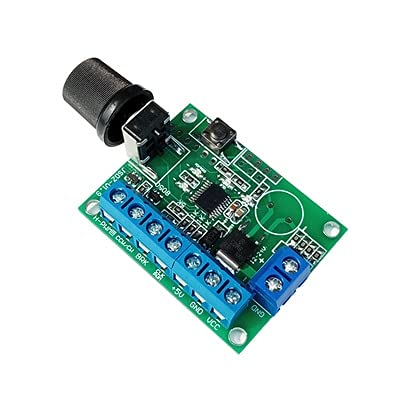
Figure 3.3: An example of a DC motor speed controller board. This type of board is typically required to operate and control the speed of brushless DC motors like the 48F704M170. Note that this controller is not included with the motor.
4. Operating Instructions
Once the motor is correctly installed and wired to a compatible controller and power supply, follow these general operating guidelines:
- Power On: Apply 12V DC power to the motor controller. The controller should then provide the necessary signals to the motor.
- Speed Control: Adjust the speed using the control mechanism on your motor controller (e.g., potentiometer, digital input). The motor's input range is 50-275 Hz for optimal fan operation.
- Monitoring: If your system utilizes the FG (Frequency Generator) output, monitor this signal to confirm the motor's operational speed.
- Power Off: Disconnect power from the motor controller when operation is complete.
Avoid operating the motor beyond its specified voltage and current limits to prevent overheating and damage.
5. Maintenance
Brushless DC motors like the 48F704M170 require minimal maintenance due to their design. However, regular checks can extend their lifespan and ensure optimal performance.
- Cleaning: Keep the motor free from dust and debris. Use a soft, dry cloth or compressed air to clean the exterior. Do not use liquids or solvents.
- Connections: Periodically inspect all electrical connections to ensure they are secure and free from corrosion.
- Mounting: Check mounting screws for tightness to prevent vibration and potential damage.
- Bearings: The motor's bearings are typically sealed and do not require lubrication. If unusual noise or resistance is detected, the motor may require professional inspection.
6. Troubleshooting
If you encounter issues with your motor, refer to the following troubleshooting guide:
| Problem | Possible Cause | Solution |
|---|---|---|
| Motor does not spin | No power, incorrect wiring, faulty controller, motor damage. |
|
| Motor spins erratically or at incorrect speed | Faulty speed signal, unstable power, controller issue, Hall sensor issue. |
|
| Motor is overheating | Overload, insufficient ventilation, prolonged operation at high current. |
|
If these steps do not resolve the issue, contact the seller or manufacturer for further assistance.
7. Specifications
| Feature | Specification |
|---|---|
| Model | 48F704M170 |
| Brand | Generic (Nidec design/component) |
| Type | DC Brushless External Rotor Motor |
| Voltage | 12V DC |
| Current | 2.5 Amps (approx.) |
| Speed | 1100 RPM (approx.) |
| Frequency Input Range | 50-275 Hz (for fan applications) |
| Features | Variable Frequency, Hall Sensor Integrated |
| Application | Suitable for DC Fan applications |
| Total Length | 8.8 cm |
| Shaft Length | 5.3 cm |
| Shaft Diameter | 0.8 cm |
| Motor Body Diameter | 6.1 cm |
| Motor Body Thickness | 2.5 cm |
| ASIN | B0BRCV9S8Q |
8. Warranty and Support
Specific warranty terms for the Generic Nidec 12V DC Brushless Motor 48F704M170 are typically provided by the seller at the time of purchase. Please retain your proof of purchase for any warranty claims.
For technical support, troubleshooting assistance beyond this manual, or warranty inquiries, please contact the retailer or manufacturer directly. Provide your product model number (48F704M170) and ASIN (B0BRCV9S8Q) when seeking support.