1. Product Overview
The MiiElAOD Mini High-Speed DAPLink-HS is a compact and efficient debug probe designed for ARM Cortex-M microcontrollers. It features a TYPE-C interface and utilizes USB 2.0 High Speed for rapid data transfer, significantly improving programming and debugging speeds compared to standard CMSIS-DAP/DAPLink probes.
This probe offers three primary functionalities: drag-and-drop programming, a serial port interface, and comprehensive debugging support. Additionally, its firmware can be updated easily via a drag-and-drop programming interface within the bootloader.

Image 1.1: MiiElAOD Mini High-Speed DAPLink-HS Debug Probe and included Type-C cable.
2. Package Contents
Verify that all items are present in your package:
- 1 x Mini High-Speed DAPLink-HS Debug Probe
- 1 x USB Type-C Cable
3. Setup Guide
3.1 Connecting the Probe
- Connect the Mini High-Speed DAPLink-HS Debug Probe to your computer using the provided USB Type-C cable.
- Connect the debug probe to your target ARM Cortex-M MCU board using the appropriate JTAG or SWD interface pins. Ensure correct pin alignment (e.g., TDI, TDO, nRST, U_TX, U_RX, TCK/CK, GND, 3V3, 5V).

Image 3.1: Top view of the DAPLink-HS Debug Probe, highlighting the Type-C port and debug pin headers.

Image 3.2: Bottom view of the DAPLink-HS Debug Probe, illustrating the pinout for connection to a target board.
3.2 Driver Installation
The DAPLink-HS probe typically enumerates as a standard USB device. For Windows, Linux, and Mac operating systems, necessary drivers are often installed automatically. If issues arise, consult the official MiiElAOD support resources for specific driver packages or installation instructions.
4. Operation
4.1 Debugging and Programming
The DAPLink-HS supports debugging and programming for ARM Cortex-M based MCUs (e.g., STM32, GD32, NRF51/52) using JTAG and SWD interfaces. It is compatible with various development environments and tools:
- Keil MDK
- IAR Workbench
- pyOCD
- OpenOCD
Refer to the documentation of your chosen development environment for specific configuration steps to use the DAPLink-HS probe.
4.2 USB Serial Port
The probe provides a USB serial port interface, allowing for communication with the target MCU. This can be used for console output, data logging, or sending commands to your embedded application.
4.3 Drag-and-Drop Programming
The DAPLink-HS supports drag-and-drop programming. When connected to a computer, the probe may enumerate as a mass storage device. Firmware files (e.g., .hex, .bin) can be dragged directly onto this virtual drive to program the target MCU. The target board will automatically reset upon successful firmware download.
5. Firmware Update
To update the firmware of the Mini DAPLink-HS probe itself:
- Access the bootloader mode of the DAPLink-HS (specific method may vary, often involves holding a button during connection or a software command).
- Once in bootloader mode, the probe will appear as a mass storage device on your computer.
- Drag the new DAPLink-HS firmware file (provided by MiiElAOD) onto this virtual drive.
- The probe will automatically update its firmware and restart.
6. Technical Specifications
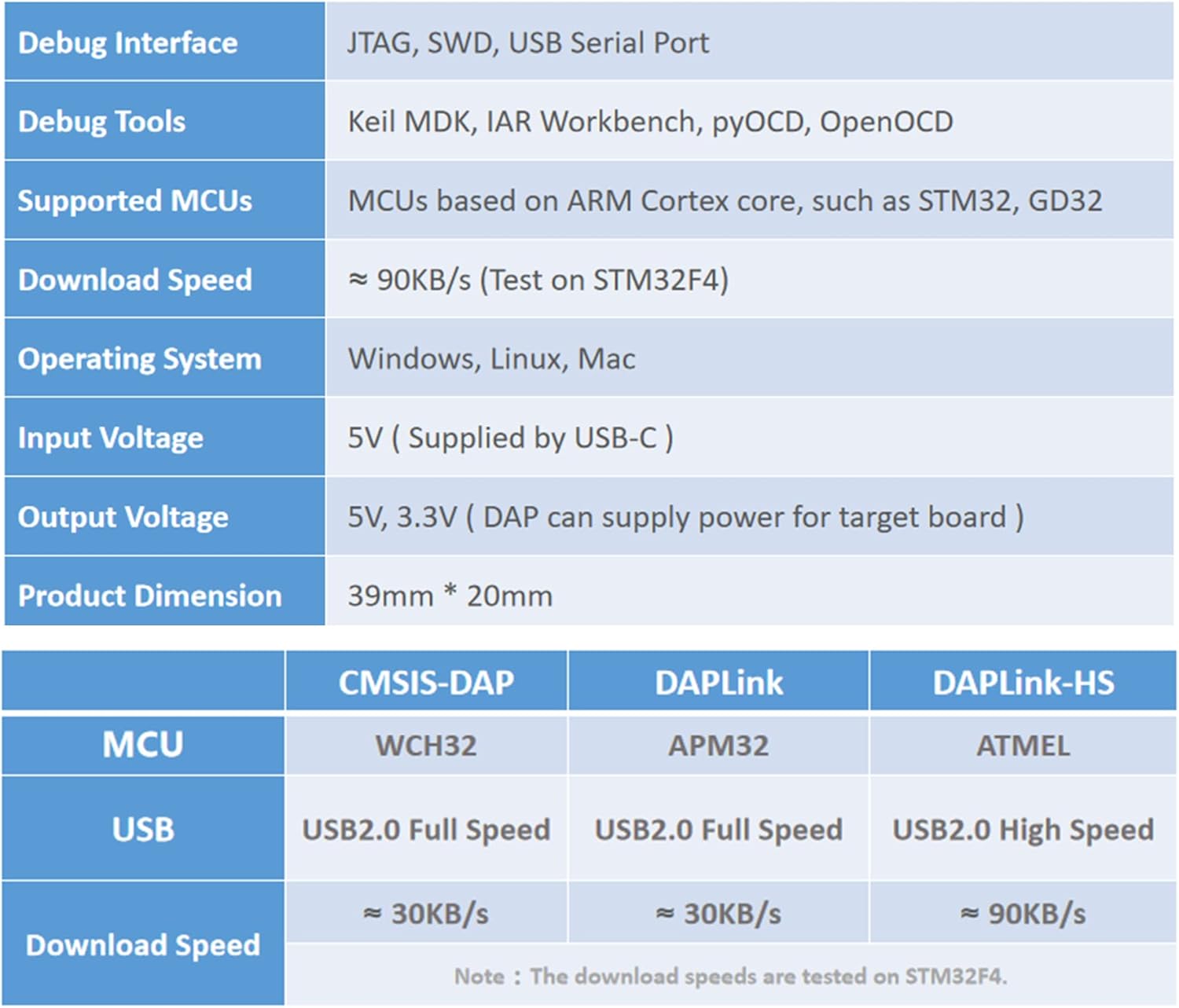
Image 6.1: Summary of DAPLink-HS technical specifications.
| Feature | Description |
|---|---|
| Debug Interface | JTAG, SWD, USB Serial Port |
| Debug Tools | Keil MDK, IAR Workbench, pyOCD, OpenOCD |
| Supported MCUs | MCUs based on ARM Cortex core (e.g., STM32, GD32, NRF51/52) |
| Download Speed | ~90KB/s (Tested on STM32F4) |
| Operating System Support | Windows, Linux, Mac |
| Input Voltage | 5V (supplied by USB-C) |
| Output Voltage | 5V, 3.3V (DAP can supply power for target board) |
| Product Dimension | 39mm * 20mm |
| USB Interface | USB 2.0 High Speed |
| Processor Brand | ARM |
7. Troubleshooting
7.1 Connection Issues
- Probe not recognized: Ensure the USB Type-C cable is securely connected to both the probe and your computer. Try a different USB port or cable. Verify that necessary drivers are installed (refer to Section 3.2).
- Target MCU not detected: Check the physical connections between the debug probe and the target board. Ensure correct pinout for JTAG/SWD. Verify that the target board is powered correctly.
7.2 Programming/Debugging Failures
- Firmware download fails: Confirm the firmware file is valid and compatible with your target MCU. Ensure the target MCU is in a state ready for programming. Check for power supply issues to the target board.
- Debugging errors: Verify your development environment's debugger settings match the DAPLink-HS probe and target MCU. Ensure the target MCU's clock and reset lines are stable.
8. Maintenance
The Mini High-Speed DAPLink-HS Debug Probe requires minimal maintenance. Keep the device clean and free from dust and moisture. Store it in a dry environment when not in use. Avoid exposing it to extreme temperatures or physical shock.
9. Support
For further assistance, technical support, or to inquire about warranty information, please visit the official MiiElAOD website or contact their customer service department. Refer to your purchase documentation for specific contact details.
Online resources may include: