Product Overview
This manual provides essential information for the use and maintenance of the TA384 Replacement Rigid Probe Tips. These tips are designed as accessories for test and measurement applications, specifically compatible with Pico Technology TA375 and TA386 oscilloscope probes.
Each package contains 5 rigid probe tips, weighing approximately 50 grams in total. They serve as crucial components for accurate signal acquisition in various testing scenarios.

Image 1: A set of five TA384 Replacement Rigid Probe Tips. Each tip features a black insulated body and a pointed gold-colored metal contact, designed for precise electrical measurements.
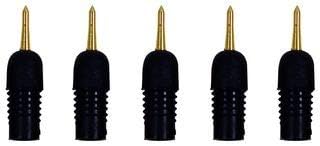
Image 2: Another view of the five TA384 Replacement Rigid Probe Tips, highlighting their compact design and the robust construction of the probe tip and body.
Setup
The TA384 rigid probe tips are designed for quick and easy replacement on compatible oscilloscope probes. Follow these steps for proper setup:
- Identify Compatible Probe: Ensure you are using a Pico Technology TA375 or TA386 oscilloscope probe. These tips are specifically designed for these models.
- Remove Old Tip (if applicable): Carefully unscrew or pull off the existing probe tip from your oscilloscope probe. Handle with care to avoid damaging the probe body.
- Attach New Tip: Align the base of the TA384 rigid probe tip with the receptacle on your oscilloscope probe. Gently push or screw the new tip into place until it is securely seated. Ensure a firm connection to guarantee accurate readings.
- Verify Connection: Lightly tug on the attached tip to confirm it is securely fastened and will not detach during use.
No additional tools or calibration are typically required for the installation of these replacement tips.
Operating Instructions
Once the TA384 rigid probe tip is securely attached to your Pico Technology oscilloscope probe, it is ready for use in your test and measurement applications. Always adhere to standard safety procedures for electrical testing.
- Connect Probe: Connect your oscilloscope probe (with the TA384 tip attached) to the appropriate input channel of your oscilloscope.
- Select Measurement Point: Carefully position the rigid probe tip onto the circuit or component test point. The fine point allows for precise contact on small terminals or densely populated circuit boards.
- Maintain Stable Contact: Ensure stable and consistent contact between the probe tip and the measurement point to obtain accurate and reliable readings. Avoid applying excessive force, which could damage the tip or the circuit.
- Observe Readings: Monitor the waveform or measurement data on your oscilloscope screen.
- Disconnect Safely: After measurement, carefully remove the probe tip from the test point.
These tips are passive components and do not require power or specific operational modes beyond the functionality of the oscilloscope probe itself.
Maintenance
Proper maintenance extends the lifespan and ensures the accuracy of your TA384 rigid probe tips.
- Cleaning: After use, especially if exposed to flux or other residues, gently clean the metal tip with a soft, lint-free cloth. If necessary, use a small amount of isopropyl alcohol. Ensure the tip is completely dry before storage or next use.
- Inspection: Regularly inspect the tip for any signs of bending, dullness, or corrosion. A damaged tip can lead to inaccurate measurements or damage to the circuit under test. Replace damaged tips immediately.
- Storage: Store the probe tips in a clean, dry environment, preferably in their original packaging or a dedicated probe accessory case, to protect them from physical damage and environmental contaminants.
- Handling: Avoid dropping the tips or subjecting them to excessive mechanical stress, as this can deform the delicate metal point.
Troubleshooting
If you encounter issues while using the TA384 rigid probe tips, consider the following common problems and solutions:
| Problem | Possible Cause | Solution |
|---|---|---|
| Inaccurate or erratic readings | Loose connection of the tip to the probe; dirty or corroded tip; damaged tip. | Ensure the tip is securely fastened. Clean the tip. Replace the tip if damaged. |
| Tip does not fit the probe | Incorrect probe model; tip not aligned correctly. | Verify your oscilloscope probe is a Pico Technology TA375 or TA386. Re-align and gently re-attempt attachment. |
| Physical damage to the tip | Accidental bending or dropping; excessive force during use. | The tip is not repairable. Replace with a new TA384 tip. |
If problems persist, consult the manual for your specific oscilloscope probe or contact the manufacturer's support.
Specifications
| Attribute | Detail |
|---|---|
| Accessory Type | Rigid Probe Tip |
| Model Number | TA384 |
| Manufacturer | PICO TECHNOLOGY |
| Quantity per Pack | 5 |
| Approximate Weight | 50 grams (total for pack) |
| Compatible Probes | Pico Technology TA375, TA386 Oscilloscope Probes |
| Batteries Included? | No |
| ASIN | B0BQMLK824 |
| First Available Date | December 20, 2022 |
Warranty and Support
Specific warranty information for the TA384 Replacement Rigid Probe Tips is not provided in the product data. For details regarding warranty coverage, please refer to the terms and conditions of your original purchase or contact the seller directly.
For technical support related to the use of these probe tips with Pico Technology oscilloscope probes, please consult the official Pico Technology documentation or their customer support channels. For general inquiries about the product, contact the retailer from whom the product was purchased.