1. Important Safety Instructions
Please read and understand all safety instructions before using the Godox DP600III-V Studio Flash Light. Improper use can result in electric shock, fire, or other hazards.
- Do not disassemble or modify the unit. Repairs should only be performed by authorized service personnel.
- Keep the unit dry. Do not handle with wet hands or immerse in water.
- Ensure proper ventilation. Do not cover the ventilation openings during operation.
- Use only the specified power cord and connect to a power source with the correct voltage.
- Avoid direct eye exposure to the flash light, as it can cause temporary vision impairment.
- Keep out of reach of children.
2. Product Overview
2.1 Package Contents
Verify that all items are present in your package:
- Godox DP600III-V Flash Light Unit
- Power Cord
- Lamp Protection Cover

Image 2.1: The Godox DP600III-V Studio Flash Light with its standard accessories, including the power cord and lamp protection cover.
2.2 Key Features
- Integrated Godox 2.4G Wireless X System: Enables wireless control of flash power, modeling lamp, and buzzer functions.
- Fast Recycling and Short Flash Duration: Offers 0.1-1 second recycling time and flash durations from 1/2000 to 1/800 second.
- Precise Power Control: Adjustable in 61 steps from 1/64 to 1/1.
- Anti-Preflash Function: Allows synchronization with cameras that utilize a single pre-flash system.
- Adjustable 30W Modeling Lamp: Brightness can be adjusted from 5% to 100%.
- Bowens Mount Compatibility: Supports a wide range of light modifiers.
- Setting Memory: Retains adjusted settings after 3 seconds and restores them upon restart.
2.3 Component Identification

Image 2.2: Detailed view of the DP600III-V control panel, showing the display, adjustment dial, and function buttons.
- Bowens Mount: Front attachment point for light modifiers.
- Flash Tube & Modeling Lamp: Light source components.
- Control Panel: LCD display, adjustment dial, and buttons for settings.
- Wireless Control Port: For external wireless triggers.
- Power Switch: To turn the unit on or off.
- Power Input: For connecting the AC power cord.
- Mounting Bracket: For attaching the flash to a light stand.

Image 2.3: Close-up of the flash tube and the 30W LED modeling lamp, located at the front of the unit.
3. Setup
3.1 Mounting the Flash Unit
- Securely attach the DP600III-V flash unit to a compatible light stand using its mounting bracket. Ensure the locking knob is tightened to prevent accidental movement.
- Adjust the tilt angle of the flash as needed and secure it with the tilt locking lever.

Image 3.1: The DP600III-V flash unit securely mounted on a light stand, demonstrating its stability and readiness for use with a reflector.
3.2 Power Connection
- Connect the provided power cord to the power input on the rear of the flash unit.
- Plug the other end of the power cord into a suitable AC power outlet.
3.3 Attaching Light Modifiers
The DP600III-V features a Bowens mount for attaching various light modifiers (e.g., softboxes, reflectors, snoots).
- Align the modifier's mounting ring with the Bowens mount on the flash unit.
- Insert the modifier and rotate it clockwise until it clicks into place, indicating it is securely locked.
- To remove, press the release button on the Bowens mount and rotate the modifier counter-clockwise.
4. Operating Instructions
4.1 Powering On/Off
Toggle the power switch located on the control panel to turn the flash unit ON or OFF.
4.2 Adjusting Flash Output
The flash output can be adjusted from 1/64 to 1/1 in 61 precise steps.
- Turn the adjustment dial on the control panel to increase or decrease the flash power.
- The current power setting will be displayed on the LCD screen.
4.3 Modeling Lamp Operation
The 30W modeling lamp assists in previewing lighting effects and can be adjusted from 5% to 100% brightness.
- Press the modeling lamp button (often labeled with a light bulb icon) to cycle through modes: OFF, PROP (proportional to flash power), or Percentage (adjustable brightness).
- When in Percentage mode, use the adjustment dial to set the desired brightness level.

Image 4.1: The modeling lamp illuminating a subject, demonstrating its utility for previewing light and its adjustable brightness feature.
4.4 Wireless X System Setup
The built-in Godox 2.4G Wireless X System allows for remote control using compatible Godox triggers (e.g., X2, XPro, XT16, FT-16).
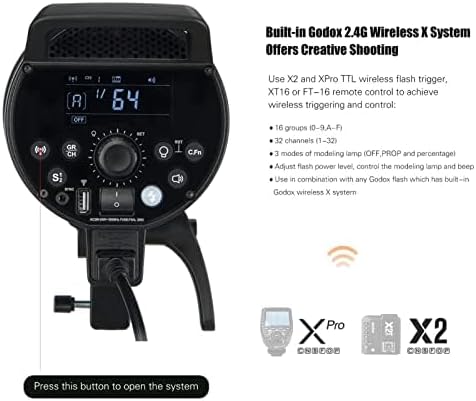
Image 4.2: The rear panel of the DP600III-V, highlighting the controls for the integrated 2.4G Wireless X System, including channel and group settings.
- Set Channel (CH): Press the CH/GR button and use the dial to select a channel (1-32). Ensure your trigger is set to the same channel.
- Set Group (GR): Press the CH/GR button again and use the dial to select a group (A-F). Match this with your trigger's group setting.
- Set ID (Optional): For advanced interference avoidance, some triggers support an ID function (01-99). Consult your trigger's manual for setup.
- Synchronization: Once channels and groups match, the flash will synchronize with the trigger, allowing remote adjustment of settings and firing.

Image 4.3: Illustration of the Godox DP600III-V being controlled wirelessly by a compatible trigger and a smartphone application, demonstrating the flexibility of the 2.4G Wireless X System.
4.5 Anti-Preflash Function
This function allows the DP600III-V to synchronize with cameras that emit a pre-flash for exposure measurement.
- Locate the S1/S2 button on the control panel.
- Press the button to toggle between S1 (standard optical slave) and S2 (anti-preflash optical slave) modes. Select S2 if your camera uses a pre-flash.
4.6 Memory Function
The flash unit automatically saves your last settings after 3 seconds of inactivity and restores them upon powering on, ensuring consistent workflow.
5. Maintenance
5.1 Cleaning
- Always disconnect the power cord before cleaning.
- Use a soft, dry cloth to wipe the exterior of the flash unit.
- For stubborn dirt, a slightly damp cloth with mild detergent can be used, followed by a dry cloth.
- Do not use harsh chemicals, solvents, or abrasive cleaners.
- Gently clean the flash tube and modeling lamp with a lint-free cloth.
5.2 Storage
- Store the flash unit in a cool, dry place, away from direct sunlight and excessive humidity.
- Attach the lamp protection cover when not in use to protect the flash tube and modeling lamp.
- If storing for extended periods, periodically check the unit.
6. Troubleshooting
This section addresses common issues you might encounter with your Godox DP600III-V flash unit.
| Problem | Possible Cause | Solution |
|---|---|---|
| Flash not firing | No power; Trigger not synchronized; Flash in sleep mode; Overheating protection activated. | Check power connection; Verify trigger channel/group settings; Press test button to wake up; Allow unit to cool down. |
| Inconsistent flash output | Low power supply; Unit not fully recycled; Incorrect trigger settings. | Ensure stable power; Wait for recycle indicator; Recheck trigger settings. |
| Wireless connection issues | Mismatched channel/group/ID; Interference; Trigger out of range. | Verify all wireless settings match; Change channel/ID; Move trigger closer to flash. |
| Modeling lamp not working | Lamp mode set to OFF; Lamp failure. | Check modeling lamp mode settings; Contact support if lamp is faulty. |
7. Specifications
| Feature | Specification |
|---|---|
| Model | DP600III-V |
| Max Power | 600Ws |
| Guide Number (GN) | GN106 (m ISO 100, with standard reflector) |
| Color Temperature | 5600K ± 200K |
| Flash Duration | 1/2000 to 1/800 seconds |
| Recycle Time | 0.1-1 seconds |
| Power Output Control | 61 steps (1/64 to 1/1) |
| Modeling Lamp | 30W LED, adjustable brightness (5% to 100%) |
| Wireless Function | Built-in Godox 2.4G Wireless X System |
| Channels | 32 (1-32) |
| Groups | 16 (0-9, A-F) |
| Sync Mode | S1/S2 Optical Slave, Sync Cord Jack |
| Mount Type | Bowens Mount |
| Item Weight | 9.23 pounds (approx. 4.19 kg) |
| Package Dimensions | 16.3 x 8.8 x 7.7 inches (approx. 41.4 x 22.4 x 19.6 cm) |
8. Warranty and Support
8.1 Warranty Information
Godox products typically come with a limited manufacturer's warranty. Please refer to the warranty card included with your product or visit the official Godox website for detailed warranty terms and conditions specific to your region. Keep your proof of purchase for warranty claims.
8.2 Customer Support
For technical assistance, troubleshooting, or service inquiries, please contact Godox customer support through their official channels. You can find more information and contact details by visiting the official Godox store or website: