AIOMEST AI-7200
AIOMEST AI-7200B Digital Clamp Meter User Manual
True RMS 6000 Counts Multimeter with NCV
1. Introduction
The AIOMEST AI-7200B is a True RMS digital clamp meter designed for safe and accurate measurement of various electrical parameters. This instrument is suitable for commercial and residential electrical troubleshooting, offering comprehensive functions for professional use. It features a 6000-count display, automatic range control, and a backlit LCD for clear readings in diverse lighting conditions.
2. Safety Information
WARNING: To avoid electric shock or personal injury, read and understand all safety information before using this product.
- Always adhere to local and national safety codes.
- Do not use the meter if it appears damaged or if the test leads are damaged.
- Do not apply more than the rated voltage, as marked on the meter, between the terminals or between any terminal and earth ground.
- Use caution when working with voltages above 30V AC RMS, 42V peak, or 60V DC. These voltages pose a shock hazard.
- Keep fingers behind the finger guards on the test probes during use.
- Replace the battery immediately when the low battery indicator appears to ensure accurate readings.
- The meter is designed with double insulation and meets safety standard IEC 61010-1, CAT III 600V.
3. Product Overview
3.1. Meter Components
Familiarize yourself with the main parts of your AIOMEST AI-7200B clamp meter.

Image 3.1: Labeled diagram of the AIOMEST AI-7200B Digital Clamp Meter, showing the current clamp, head lamp, clamp head switch, HOLD key, SEL key, Max/Min key, COM socket, rotary switch, Hz% key, and LCD backlight screen.
- Current Clamp: Used for non-contact AC/DC current measurement. Opens up to 26mm to enclose a conductor.
- Head Lamp: Illuminates the measurement area.
- Rotary Switch: Selects measurement functions.
- LCD Backlight Screen: Displays measurement readings and function indicators.
- Function Buttons: HOLD, SEL, Max/Min, REL, Hz%.
- Input Jacks (COM, VΩHz): For connecting test leads for voltage, resistance, capacitance, frequency, diode, and continuity measurements.
3.2. Display Features
The LCD provides various indicators for selected functions and measurement results.
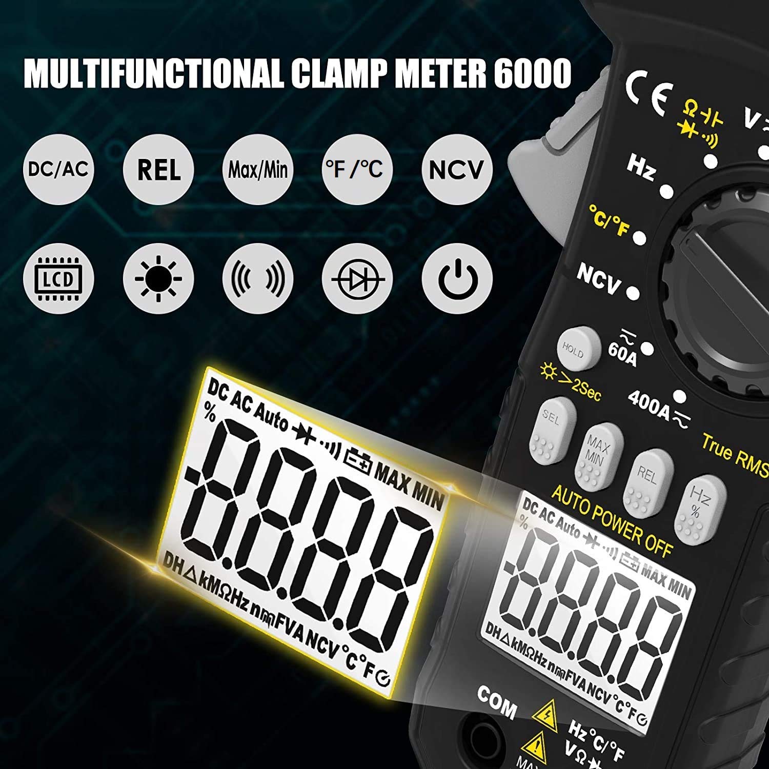
Image 3.2: The AIOMEST AI-7200B clamp meter's LCD screen, illustrating icons for DC/AC, Relative Value (REL), Max/Min, Celsius/Fahrenheit (°F/°C), Non-Contact Voltage (NCV), Hertz (Hz), LCD backlight, flashlight, continuity, diode, and power on/off.
- 6000 Counts Display: High-resolution digital readout.
- Backlight: Improves visibility in low-light conditions.
- Function Indicators: Icons for AC/DC, Hz, Ω, V, A, °C/°F, NCV, Diode, Continuity, Data Hold, Max/Min, Relative Value.
- Low Battery Indication: Alerts when battery replacement is needed.
- Over Range Indication: Displays "OL" when the measurement exceeds the selected range.
4. Setup
4.1. Battery Installation
The meter requires two 1.5V AAA batteries for operation.
- Locate the battery compartment cover on the back of the meter.
- Use a screwdriver to loosen the screw on the battery cover.
- Remove the cover and insert two 1.5V AAA batteries, observing the correct polarity (+ and -).
- Replace the battery cover and tighten the screw.
4.2. Connecting Test Leads
For measurements requiring test leads (voltage, resistance, capacitance, frequency, diode, continuity, temperature), connect them as follows:
- Insert the black test lead into the COM (common) input jack.
- Insert the red test lead into the VΩHz input jack.
- For temperature measurement, connect the temperature probe into the COM and VΩHz jacks, observing polarity if applicable.
5. Operating Instructions
5.1. General Operation
- Power On/Off: Turn the rotary switch from OFF to any function to power on. Turn to OFF to power off.
- Auto Range Control: The meter automatically selects the appropriate measurement range.
- Backlight: Press the backlight button (often integrated with HOLD or a dedicated button) to turn the LCD backlight on/off.
- Data Hold (HOLD): Press the HOLD button to freeze the current reading on the display. Press again to release.
- Max/Min: Press the Max/Min button to record the maximum and minimum values during a measurement. Press again to cycle through Max, Min, and current reading.
- Relative Value (REL): Press the REL button to store the current reading as a reference and display subsequent measurements as a deviation from this reference.
- Automatic Shutdown: The meter will automatically power off after approximately 15 minutes of inactivity to conserve battery life.
5.2. Measuring AC/DC Voltage
- Connect the test leads: black to COM, red to VΩHz.
- Turn the rotary switch to the V (Voltage) position. The meter will automatically detect AC or DC voltage.
- Touch the test probes to the circuit points where voltage is to be measured.
- Read the voltage value on the LCD.
5.3. Measuring AC/DC Current (Clamp Function)
The clamp function allows for non-contact current measurement.

Image 5.3: Illustration demonstrating the correct method of clamping a single conductor for accurate current measurement (right) versus an incorrect method where multiple conductors are clamped, leading to inaccurate readings (left).
- Turn the rotary switch to the A (Current) position (e.g., 60A or 400A). The meter will automatically detect AC or DC current.
- Open the clamp jaws by pressing the clamp head switch.
- Enclose only one conductor (not a power cord with multiple wires) within the clamp jaws. Ensure the jaws are fully closed.
- Read the current value on the LCD. For DC current, if the reading is unstable at low values, use the REL function to zero out the display before clamping.
5.4. Measuring Resistance
- Connect the test leads: black to COM, red to VΩHz.
- Turn the rotary switch to the Ω (Resistance) position.
- Ensure the circuit or component under test is de-energized.
- Touch the test probes across the component or circuit to measure resistance.
- Read the resistance value on the LCD.
5.5. Measuring Capacitance
- Connect the test leads: black to COM, red to VΩHz.
- Turn the rotary switch to the Capacitance position (often shared with Ω or Diode). Use the SEL button to select Capacitance if needed.
- Ensure the capacitor is fully discharged before testing.
- Touch the test probes across the capacitor terminals.
- Read the capacitance value on the LCD.
5.6. Measuring Frequency
- Connect the test leads: black to COM, red to VΩHz.
- Turn the rotary switch to the Hz (Frequency) position.
- Touch the test probes to the circuit points where frequency is to be measured.
- Read the frequency value on the LCD.
5.7. Temperature Measurement
The meter can measure temperature using a K-type thermocouple (included).

Image 5.7: The AIOMEST AI-7200B clamp meter displaying a temperature reading while a temperature probe is immersed in a glass of water, demonstrating its temperature measurement capability.
- Connect the temperature probe to the COM and VΩHz input jacks.
- Turn the rotary switch to the °C/°F (Temperature) position.
- Press the SEL button to switch between Celsius (°C) and Fahrenheit (°F).
- Place the tip of the temperature probe on or in the object/environment to be measured.
- Read the temperature value on the LCD.
5.8. Diode Test
- Connect the test leads: black to COM, red to VΩHz.
- Turn the rotary switch to the Diode position (often shared with Continuity). Use the SEL button to select Diode if needed.
- Touch the red probe to the anode and the black probe to the cathode of the diode.
- The display will show the forward voltage drop. Reverse the probes; the display should show "OL" for an open circuit.
5.9. Continuity Test
- Connect the test leads: black to COM, red to VΩHz.
- Turn the rotary switch to the Continuity position (often shared with Diode). Use the SEL button to select Continuity if needed.
- Touch the test probes across the circuit or component.
- If the resistance is below a certain threshold (typically <50Ω), the buzzer will sound, indicating continuity.
5.10. Non-Contact Voltage (NCV) Detection
The NCV function allows for detecting AC voltage without direct contact.

Image 5.10: The AIOMEST AI-7200B clamp meter's NCV function in action, showing the meter's head near an electrical outlet with a flashlight illuminating and 'BEEP' indicators, signifying non-contact voltage detection.
- Turn the rotary switch to the NCV position.
- Move the meter's NCV sensor (located at the top of the clamp head) close to the conductor or outlet.
- If AC voltage is detected, the flashlight will light up, and the buzzer will sound, with the frequency of beeps increasing with stronger signals.
6. Specifications
| Parameter | Range | Accuracy |
|---|---|---|
| Display | 6000 Counts | |
| AC Voltage | 6V/60V 600V | ±(1.0%+3) ±(1.5%+3) |
| DC Voltage | 600mV/6V/60V 600V | ±(0.5%+2) ±(0.8%+2) |
| AC Current | 60A 400A/10A | ±(2%+10) ±(3.0%+10) |
| DC Current | 60A 400A/10A | ±(2%+10) ±(3.0%+10) |
| Resistance | 600Ω 6kΩ/60kΩ/600kΩ/6MΩ 60MΩ | ±(1.0%+3) ±(1.0%+2) ±(1.5%+3) |
| Frequency | 9.999Hz~9.999MHz | ±(0.1%+5) |
| Jaw Caliber | 1 inch (26mm) | |
| Dimensions | 8.15in x 2.95in x 1.46in (270mm x 75mm x 37mm) | |
| Weight | 9.88 oz (280g) | |
| Safety Rating | IEC 61010-1, CAT III 600V, Double Insulation | |
| Power Source | 2 x 1.5V AAA Batteries | |
| Automatic Shutdown | Approx. 15 minutes of inactivity | |
7. Maintenance
7.1. General Care
- Keep the meter dry. If it gets wet, wipe it dry.
- Use and store the meter in normal temperature environments. Extreme temperatures can shorten the life of electronic devices.
- Handle the meter gently and carefully. Dropping it can damage the circuit boards and cases.
- Keep the meter away from dust and dirt, which can cause premature wear of parts.
- Wipe the meter with a damp cloth occasionally to keep it looking new. Do not use harsh chemicals, cleaning solvents, or strong detergents.
7.2. Battery Replacement
When the low battery indicator appears on the display, replace the batteries as soon as possible to ensure accurate measurements.
- Ensure the meter is powered off and disconnect all test leads from any circuit.
- Follow the steps outlined in Section 4.1 Battery Installation to replace the two 1.5V AAA batteries.
8. Troubleshooting
This section addresses common issues you might encounter with your AIOMEST AI-7200B clamp meter.
- Meter does not power on: Check if the batteries are correctly installed and have sufficient charge. Replace batteries if necessary.
- "OL" displayed: This indicates an over-range condition. The measured value exceeds the meter's current range. Select a higher range if available, or ensure the measurement is within the meter's capabilities. For continuity, it means an open circuit.
- Inaccurate readings:
- Ensure test leads are fully inserted and not damaged.
- Check battery level; low batteries can affect accuracy.
- For current measurement, ensure only one conductor is clamped.
- For DC current, use the REL function to zero out the display before clamping if there's an initial offset.
- No NCV detection: Ensure the NCV sensor is positioned correctly near the AC voltage source. The NCV function detects AC voltage only.
- Buzzer not sounding during continuity test: The resistance might be above the continuity threshold, or the circuit is open.
9. Package Contents
Verify that all items are present in your product package:

Image 9.1: The AIOMEST AI-7200B Digital Clamp Meter displayed alongside its complete set of accessories, including test leads, a temperature probe, a small screwdriver, and two AAA batteries.
- 1 x AIOMEST AI-7200B Clamp Meter
- 1 x Pair of Test Leads
- 1 x Carrying Case
- 1 x User Manual (this document)
- 2 x 1.5V AAA Batteries
- 1 x Temperature Probe (K-type thermocouple)
10. Warranty and Support
AIOMEST provides the following support for your product:
- Warranty: This product comes with a 12-month warranty from the date of purchase.
- Technical Support: Life-long technical support is available for this product. For assistance, please contact AIOMEST customer service through your purchase platform or the official AIOMEST website.
Ask a question about this manual
Ask about setup, troubleshooting, compatibility, parts, safety, or missing instructions. Manuals+ will review the question and use this page’s manual context to help answer it.