1. Product Overview
The MOOKEENONE GY500 is a single-axis heading lock digital gyro designed to enhance the stability and control of RC cars and helicopters. It features an AVCS (Active Vector Control System) for automatic rudder offset elimination and a piezoelectric sensor for effective rudder offset reduction during flight. The GY500 is compatible with digital servos and allows for remote control adjustment of sensitivity and operation mode.
Key Features:
- AVCS System: Automatically eliminates rudder offset caused by environmental factors or helicopter attitude, facilitating precise control for 3D flight.
- Piezoelectric Sensor: Reduces rudder offset during flight.
- Digital Servo (DS) Mode: Ensures full compatibility and high-speed response with digital servos.
- Remote Control Adjustment: Allows adjustment of gyroscope sensitivity and switching between lock mode and normal mode.
Package Contents:
- 1 x GY500 Gyro
- 1 x GY500 AC/DC Power Supply
2. Setup and Installation
Proper installation and setup are crucial for optimal performance of your GY500 gyro. Follow these steps carefully.
2.1 Physical Installation
Mount the GY500 gyro securely to your RC helicopter or car chassis. Ensure it is placed on a flat surface, away from vibrations and heat sources. Use double-sided foam tape for vibration dampening if necessary.
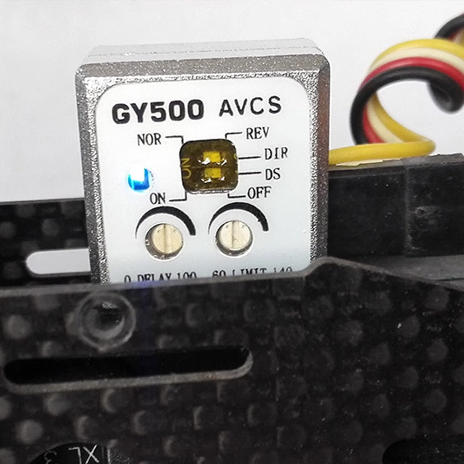
Image: The GY500 gyro mounted on an RC helicopter frame, showing its compact size and placement.

Image: A close-up view of the GY500 gyro, highlighting its control panel and the attached wiring harnesses.
2.2 Wiring Connections
Connect the GY500 to your receiver and tail servo as follows:
- Sensitivity Channel Interface: Connect this to the receiver's sensitivity channel (typically CH5). This connection allows you to adjust the gyro's sensitivity and switch between lock mode and normal mode via your remote control. The connector uses a single-core signal line; handle with care to avoid disconnection.
- Rudder Channel Interface: Connect this to the rudder channel (CH4) of the receiver.
- Tail Rudder Servo Interface: Connect this to your tail rudder servo.

Image: A detailed view of the GY500 gyro's connection ports, showing the standard servo connectors.
2.3 Initial Configuration
Before first use, configure the gyro settings on the unit itself:
- DS Mode Switch: This switch determines compatibility with your servo type.
- If using a digital servo, set the DS mode switch to the ON position.
- If using a general (analog) servo, set the DS mode switch to the OFF position.
- Caution: Setting the DS mode to ON with an analog servo may cause damage to the servo due to different output signal formats.
- Control Delay Adjustment Knob (0 DELAY 100): This knob adjusts the operating speed of the tail control signal.
- If your helicopter's tail rudder produces tracking (oscillations) with a slower steering gear, turn the knob clockwise to increase the delay time to eliminate the tracking phenomenon.
- If your tail rudder uses a high-speed servo (e.g., a digital servo), set the knob to the 0 position for minimal delay.
- Steering Gear Maximum Stroke Adjustment Knob (60 LIMIT 140): This knob sets the maximum amount of tail rudder servo travel.
- Fully steer the rudder stick to the left and right on your transmitter.
- Adjust this knob so that the stroke of the tail rudder does not exceed the maximum range of the tail pitch sleeve.
- Turn the knob clockwise to increase the stroke.

Image: The GY500 gyro's main unit, showing the "NOR-REV" switch, "ON-OFF" switch, "DIR-DS" switch, and the two adjustment knobs for Delay and Limit.
3. Operation
Understanding the operational modes and features of the GY500 gyro will help you achieve stable and precise control of your RC model.
3.1 AVCS System (Heading Lock Mode)
The AVCS system, also known as Heading Lock mode, automatically compensates for rudder offset. This means the gyro actively works to maintain the helicopter's heading, even when subjected to external forces like wind or changes in attitude. This feature makes the rudder easier to handle and is particularly beneficial for advanced maneuvers like 3D fancy flight.
When the rudder is deflected by crosswind, the gyro will resist this offset. It continuously calculates the offset angle and sends control signals to counteract the crosswind, ensuring the rudder remains stable. This automatic offset function prevents the tail from shifting even under continuous attack or during rotational movements, where the tail rudder position is determined by the angular velocity of the body rotation.
3.2 Normal Mode
In normal mode, the gyro provides stabilization but does not actively lock the heading. It assists in dampening unwanted movements but allows the pilot more direct control over the tail's position. This mode is often preferred by beginners or for specific flight styles where heading lock is not desired.
3.3 Remote Control Sensitivity and Mode Switching
The sensitivity of the gyroscope and its operation mode (lock mode or normal mode) can be adjusted directly from your remote control, provided the sensitivity channel interface is connected to your receiver's CH5. Refer to your transmitter's manual for instructions on how to assign and adjust gyro sensitivity on CH5.

Image: The GY500 gyro with its blue indicator light illuminated, signifying power or active status.
3.4 Reverse Switch (NOR-REV)
The reverse switch controls the direction of the gyro's compensation. The correct setting depends on the direction of rotation of your main rotor and the direction of your tail rudder link. If the tail moves in the wrong direction when you move the helicopter, flip this switch. Test this carefully before flight.
4. Maintenance
To ensure the longevity and reliable performance of your GY500 gyro, follow these simple maintenance guidelines:
- Keep Clean: Regularly clean the gyro unit with a soft, dry cloth. Avoid using solvents or harsh chemicals.
- Check Connections: Periodically inspect all wiring connections for looseness or damage. Secure any loose connections.
- Vibration Control: Ensure the gyro remains securely mounted and that vibration dampening materials (if used) are in good condition. Excessive vibration can negatively impact gyro performance.
- Storage: Store the gyro in a dry, cool environment, away from direct sunlight and extreme temperatures.
5. Troubleshooting
This section addresses common issues you might encounter with your GY500 gyro.
| Problem | Possible Cause | Solution |
|---|---|---|
| Tail servo slowly drives to extreme position in Heading Lock (AVCS) mode. | This behavior is normal for heading lock gyros. The gyro is actively correcting for perceived drift to maintain heading. | No action required. This indicates the gyro is functioning as intended. Ensure the servo limits are correctly set to prevent over-travel. |
| Tail rudder oscillates or "tracks" during flight. | Gyro sensitivity is too high, or the control delay is incorrect for the servo speed. |
|
| Tail servo does not respond correctly or is glitchy. |
|
|
| Gyro does not seem to be working or providing stabilization. |
|
|
6. Specifications
| Feature | Detail |
|---|---|
| Model | GY500 |
| Type | Single Axis Heading Lock Digital Gyro |
| Compatibility | RC Cars, RC Helicopters (with digital or analog servos) |
| Sensor Type | Piezoelectric |
| Dimensions (Package) | 3.94 x 3.15 x 0.79 inches |
| Item Weight | 0.352 ounces |
| Manufacturer | MOOKEENONE |
7. Warranty and Support
For warranty information and technical support, please contact the manufacturer, MOOKEENONE, or your authorized dealer. Keep your purchase receipt as proof of purchase.
For further assistance, you may refer to the product page on Amazon: MOOKEENONE GY500 Product Page