1. Introduction
This manual provides comprehensive instructions for the installation, operation, and maintenance of the Berner EL301 Photoelectric Barrier. The EL301 is a 24V wired safety device designed for both indoor and outdoor applications, serving as an additional safety measure for automated gate systems. It features an IP65 protection rating, ensuring durability in various environmental conditions, and includes a 2x10 meter connection cable for flexible setup.
The system is compatible with specific Berner gate opener models, including GA103-GA501, DA22-DA42-L, DA200SA-DA300SA, and C302-C802. It offers a reliable detection range of 1 to 8 meters. Please read these instructions carefully before proceeding with installation or operation to ensure safe and correct usage.
2. Product Features
- Versatile Application: Suitable for both indoor and outdoor environments as an additional safety device.
- High Protection Rating: IP65 rated for protection against dust and water jets.
- Extended Connectivity: Equipped with a 2 x 10 meter connection cable for flexible installation.
- Wired Safety System: Ensures reliable and consistent operation.
- Integrated Test Function: Allows for verification of proper operation.
- Wide Compatibility: Designed for use with Berner models GA103-GA501, DA22-DA42-L, DA200SA-DA300SA, and C302-C802.
- Adjustable Detection Range: Operates effectively within a range of 1 to 8 meters.
3. Package Contents
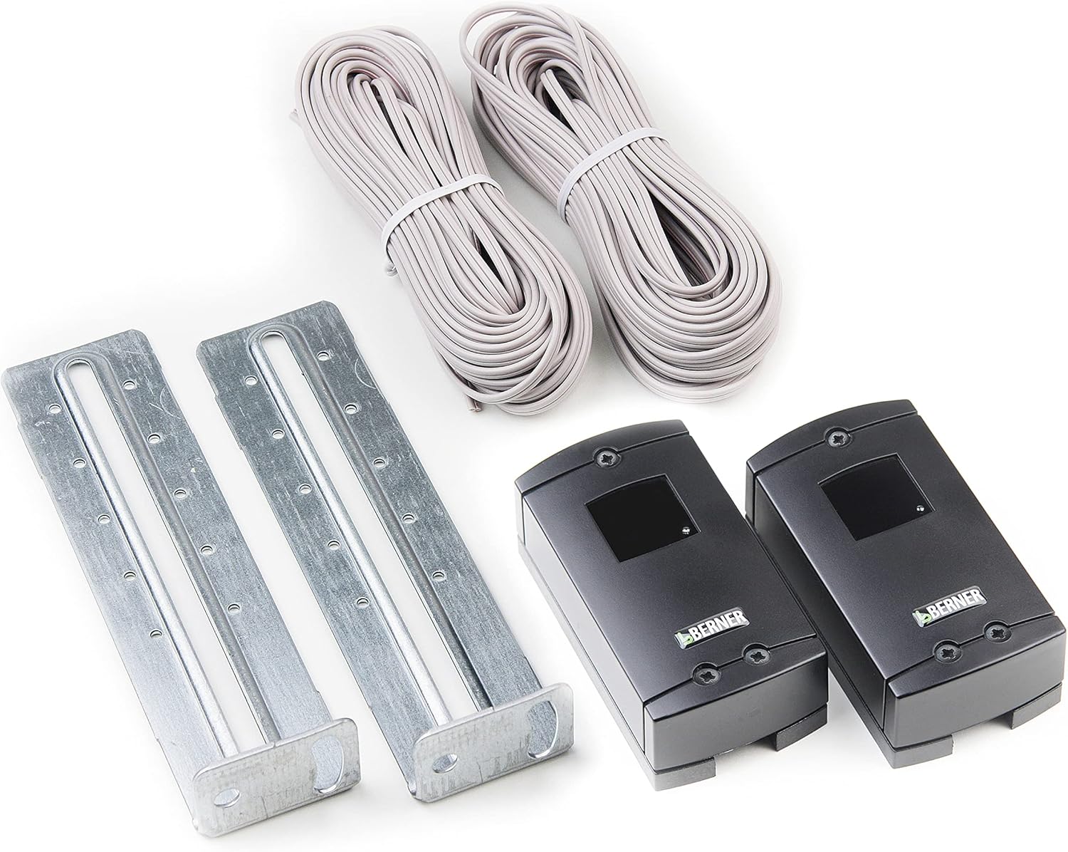
This image displays the complete Berner EL301 photoelectric barrier system. It features two compact black sensor units, each bearing the 'BERNER' logo, designed for detecting obstructions. Accompanying these are two robust metal mounting brackets, essential for secure installation. Also visible are two neatly coiled bundles of grey electrical cable, each 10 meters long, for connecting the sensors to the power supply and control unit.
Upon unpacking, please verify that all components listed below are present and undamaged:
- Berner EL301 Photoelectric Barrier (Transmitter and Receiver units)
- Connection Cable (2 x 10 meters)
- Installation Material (Mounting brackets and fasteners)
If any items are missing or damaged, please contact your supplier immediately.
4. Technical Specifications
| Specification | Value |
|---|---|
| Model Number | EL301 (Reference: 436299) |
| Brand | Berner Torantriebe |
| Power Supply | 24 V |
| Protection Rating | IP65 |
| Connection Cable Length | 2 x 10 meters |
| Wiring | 2-wire (for compatible models) |
| Detection Range | 1 - 8 meters |
| Dimensions (L x W x H) | 8.5 x 4.5 x 4.5 cm |
| Weight | 621 grams |
| Material | Aluminum (housing/mounting) |
| Included Components | Installation material |
| Batteries Required | No |
5. Setup and Installation
Proper installation is crucial for the reliable operation of the photoelectric barrier. It is recommended that installation be performed by a qualified technician.
5.1 Safety Precautions
- Ensure the power supply to the gate opener system is disconnected before beginning installation.
- Wear appropriate personal protective equipment (PPE).
- Adhere to all local electrical codes and regulations.
5.2 Mounting the Units
- Select Location: Choose a location where the transmitter and receiver units can be mounted directly opposite each other, ensuring an unobstructed line of sight across the gate opening. The recommended mounting height is typically between 50 cm and 80 cm from the ground.
- Attach Brackets: Use the provided installation material to securely fasten the metal mounting brackets to a stable surface (e.g., gate post, wall). Ensure they are level and aligned.
- Mount Sensors: Attach the photoelectric barrier units (one transmitter, one receiver) to the mounted brackets. The transmitter and receiver units are typically marked or can be identified by their wiring.
5.3 Wiring
- Connect Cables: Route the 2 x 10 meter connection cables from each photoelectric barrier unit to the control unit of your compatible Berner gate opener.
- Terminal Connection: Connect the wires according to the wiring diagram provided in your specific Berner gate opener manual. The EL301 uses a 2-wire connection. Ensure correct polarity and secure connections.
- Cable Management: Secure all cables to prevent damage and ensure a tidy installation.
5.4 Alignment and Testing
- Power On: Once all connections are secure, restore power to the gate opener system.
- Align Units: Carefully align the transmitter and receiver units. Most photoelectric barriers have indicator lights that illuminate when proper alignment is achieved. Adjust the units until the indicator light on the receiver (or both) shows a stable signal.
- Perform Test: Activate the gate opener. While the gate is closing, interrupt the beam between the photoelectric barrier units with an object (e.g., your hand or a small box). The gate should immediately stop or reverse its movement.
- Repeat Test: Perform the test multiple times at different points along the beam path to ensure consistent detection.
If the gate does not react as expected during the test, re-check alignment and wiring.
6. Operating Instructions
The Berner EL301 Photoelectric Barrier operates automatically as a safety sensor for your automated gate system. Once correctly installed and aligned, it continuously monitors the area between the transmitter and receiver units.
- Normal Operation: When the beam between the units is unobstructed, the gate opener system functions normally.
- Obstruction Detection: If an object (person, vehicle, animal) breaks the infrared beam while the gate is closing, the photoelectric barrier sends a signal to the gate opener control unit.
- Safety Response: Upon receiving the signal, the gate opener will typically stop its movement and/or reverse direction to prevent collision or entrapment. The specific response depends on the programming of your gate opener control unit.
- Test Function: The integrated test function allows for periodic verification of the barrier's functionality. Refer to Section 5.4 for details on performing a test.
The photoelectric barrier is an additional safety device and should not be relied upon as the sole safety measure. Always exercise caution when operating automated gates.
7. Maintenance
Regular maintenance ensures the longevity and reliable operation of your Berner EL301 Photoelectric Barrier.
- Cleaning: Periodically clean the lenses of both the transmitter and receiver units using a soft, damp cloth. Dust, dirt, spiderwebs, or debris can obstruct the infrared beam and cause false detections or prevent proper operation. Do not use abrasive cleaners.
- Alignment Check: Regularly check the alignment of the units. Strong winds, vibrations, or accidental impacts can cause misalignment. Re-align as necessary (refer to Section 5.4).
- Cable Inspection: Inspect the connection cables for any signs of wear, damage, or fraying. Replace damaged cables immediately to prevent electrical hazards or system malfunction.
- Functionality Test: Perform a functionality test at least once a month (refer to Section 5.4) to ensure the barrier is detecting obstructions correctly.
- Obstruction Removal: Keep the area between the photoelectric barrier units clear of any permanent obstructions, such as overgrown vegetation or stored items.
8. Troubleshooting
If you experience issues with your Berner EL301 Photoelectric Barrier, consult the following troubleshooting guide.
| Problem | Possible Cause | Solution |
|---|---|---|
| Gate does not close, or reverses immediately. |
|
|
| Photoelectric barrier does not detect obstructions. |
|
|
| Intermittent detection or false alarms. |
|
|
If the problem persists after attempting these solutions, please contact Berner customer support or a qualified technician.
9. Warranty and Support
Information regarding the specific warranty period and terms for the Berner EL301 Photoelectric Barrier is not available in this document. Please refer to your purchase documentation, the Berner Torantriebe official website, or contact your authorized Berner dealer for detailed warranty information.
For technical support, spare parts, or service inquiries, please contact Berner Torantriebe customer service or your local distributor. When contacting support, please have your product model (EL301) and reference number (436299) available.