1. Introduction
The Generic G128N Cable Continuity Tester is a specialized instrument designed for evaluating the quality and reliability of various cables, wiring harnesses, and wiring arrangements. It is suitable for testing electronic cable products such as terminal wires, USB data lines (for standard two-terminal conduction), computer peripheral cables, and other electronic connector cables. The G128N efficiently detects open circuits, short circuits, and misalignments in cables with up to 64 pins per side (128 pins total).
2. Key Features
- Comprehensive Testing: Detects short circuits, open circuits, misplacement, and instantaneous short/open circuits.
- Versatile Cable Compatibility: Capable of testing various wiring harness types, including one-to-many, many-to-many, cross-type, and cables with integrated switches.
- High Pin Count: Supports testing of wiring harnesses with up to 64 pins on each side (128 pins total).
- Automated Learning and Testing: Features automatic sample reading and testing functions for efficiency.
- Memory Function: Retains learned sample data even after power-off, eliminating the need for re-learning.
- Clear Feedback: Provides test results through visual (green/red lights) and audible (sound prompts) indicators.
- Adjustable Sound Modes: Three sound settings: off, correct prompt, or error prompt.
3. Setup
3.1 Unpacking and Physical Overview
Carefully unpack the G128N tester and its accessories. Familiarize yourself with the device's components and ports.

Figure 3.1: Front, side, and rear views of the G128N Cable Continuity Tester. The front panel features the display, control buttons, and A/B ports. The side and rear panels show the enclosure design and power input.
3.2 Connecting Test Boards and Cables
Connect the provided test boards or your custom wiring harnesses to the 'A port' and 'B port' on the front panel of the tester. Ensure connections are secure.

Figure 3.2: The G128N tester with two test boards connected to the 'A port' and 'B port' for cable testing.
3.3 Power Connection
Connect the power cable to the designated power input on the rear of the device and plug it into a suitable power outlet. Turn on the device using the 'Power Switch' on the front panel.
4. Operating Instructions
4.1 Control Panel Overview
The front panel of the G128N features a display and several control buttons for operation.

Figure 4.1: Labeled control panel of the G128N tester. Key controls include the Display, Up/Down buttons, Read button, Mode button, Power Switch, and Search Port.
- Display: Shows test results and operational messages.
- Read Button: Short press to read stored sample data for testing. Long press (3 seconds) to enter sample learning mode.
- Mode Button: Short press to switch between test modes. Long press (3 seconds) to set functions (e.g., sound settings).
- Up/Down Buttons: Used for navigation and selection within menus or for adjusting settings.
- Power Switch: Turns the device on or off.
- Search Port: Interface for the point-finding test pen.
4.2 Learning Sample Cables
To store a sample cable's configuration for future testing:
- Connect the sample cable to the A and B ports.
- In spot measurement mode, long press the Read button (leftmost button) for 3 seconds to initiate sample learning.
- Use the Up and Down keys to select the desired data storage space (up to 15 sets can be stored).
- Short press the Read button again to save the data of the connected sample cable.
4.3 Testing Stored Samples
To test a cable against a previously stored sample:
- Connect the cable to be tested to the A and B ports.
- Short press the Read button to recall the data of a stored sample cable.
- The tester will automatically compare the connected cable to the stored sample and display the results.
4.4 Test Results and Sound Settings
Test results are indicated by both visual and audible cues:
- Green Light: Indicates a correct or successful test.
- Red Light: Indicates an error (e.g., short circuit, open circuit, misplacement).
- LCD Display: Provides detailed test results and error messages.
The sound prompt can be configured by long pressing the Mode button. There are three settings:
- Off: No sound prompts.
- Correct Prompt: Sound indicates a correct test.
- Error Prompt: Sound indicates an error.
4.5 Memory Function
The G128N features a memory function that retains learned sample data and instrument settings even after the device is powered off. This means you do not need to re-learn samples or reconfigure settings each time you power on the instrument.
4.6 Connection Modes for Various Wires
The G128N can test various complex wiring configurations. The wiring method is determined by your specific cable and convenience. After connection, the wire data can be set and stored for testing.

Figure 4.2: Examples of measurable wire types, including connector loops, wiring harnesses with switches, one-to-many/many-to-one configurations, and cross/complex wiring harnesses.
The tester supports different connection methods for various cable types. Each end of the wire harness must be connected to the tester, and one end can only correspond to one port (A or B) of the tester.
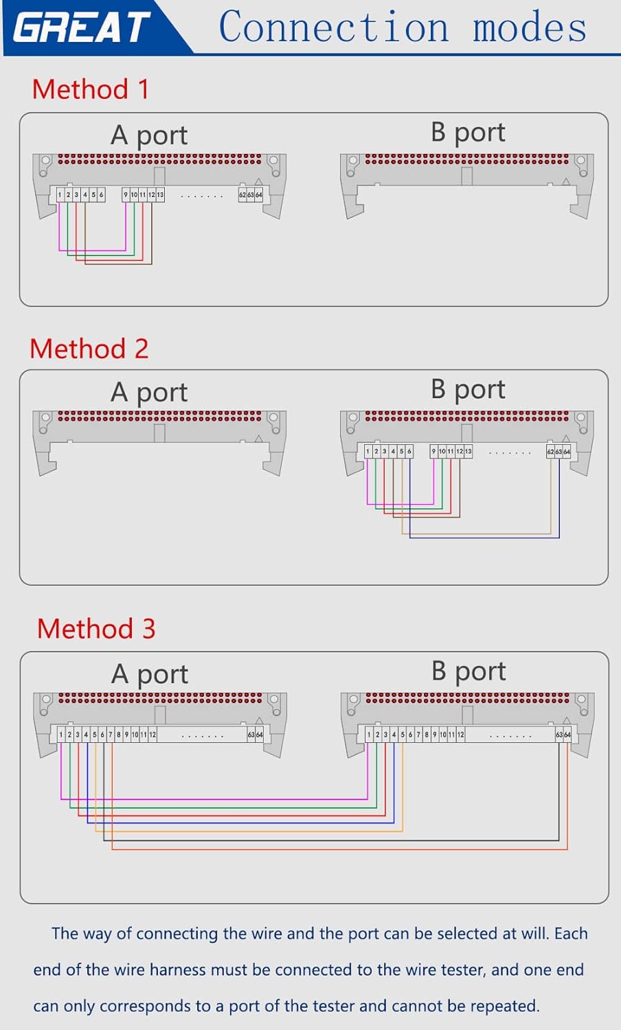
Figure 4.3: Three common connection methods (Method 1, Method 2, Method 3) illustrating how different wiring harnesses can be connected to the A and B ports for testing.
4.7 Avoiding Incorrect Wiring
When using a PVC board for testing, it is crucial to ensure correct wiring. An common error occurs when the A port leads to sockets with various spacing specifications, but all pins are incorrectly connected to a single A-port pin (e.g., all connected to A1, all connected to A2, etc.). Each pin on the test board must correspond to its unique pin on the tester.

Figure 4.4: An example of incorrect wiring (left) where multiple lines are connected to a single pin on the A port, and correct wiring (right) where each line connects to a distinct pin.
4.8 Point-Finding Test
The point-finding test is used for wires that have a connector at one end and scattered individual wires at the other end. This function helps identify the correct pin for each scattered wire.
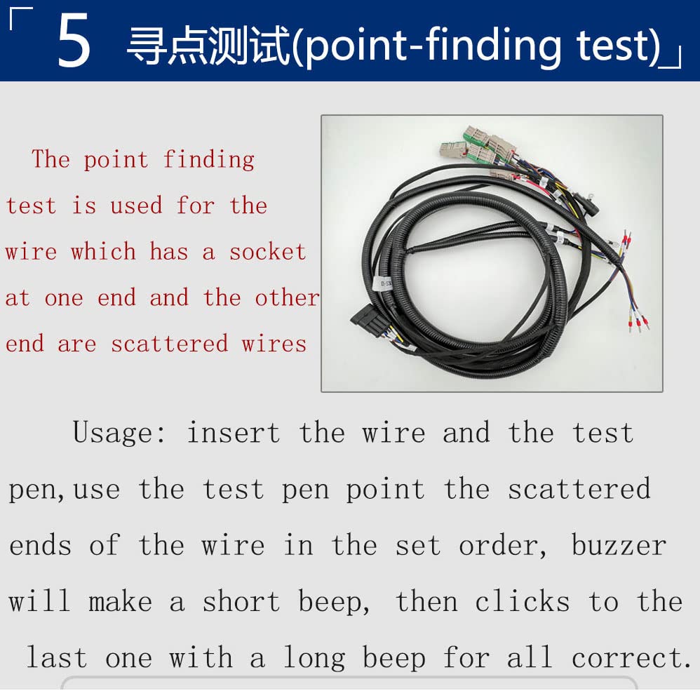
Figure 4.5: Description of the point-finding test. Insert the wire and the test pen. Use the test pen to touch the scattered ends of the wire in the set order. A short beep indicates a correct connection, and a long beep for the last correct connection confirms all are correct.
Usage: Insert the wire with the connector into the appropriate port on the tester. Connect the test pen to the 'Search Port'. Use the test pen to sequentially touch the scattered ends of the wire. The tester will emit a short beep for each correct connection. Upon identifying the last correct connection, a long beep will sound, confirming all connections are correct.
5. Maintenance
To ensure the longevity and accurate performance of your G128N Cable Continuity Tester, follow these maintenance guidelines:
- Cleaning: Regularly wipe the exterior of the device with a soft, dry cloth. Avoid using abrasive cleaners or solvents that could damage the casing or display.
- Storage: Store the tester in a clean, dry environment away from direct sunlight, extreme temperatures, and high humidity.
- Handling: Handle the device with care to prevent physical damage. Avoid dropping or subjecting it to strong impacts.
- Port Care: Keep the A and B ports, as well as the search port, free from dust and debris. Use compressed air if necessary to clear any obstructions.
- Power Off: Always power off the device when not in use for extended periods.
6. Troubleshooting
If you encounter issues with your G128N Cable Continuity Tester, refer to the following common troubleshooting steps:
- Device Not Powering On:
- Ensure the power cable is securely connected to both the device and a working power outlet.
- Verify that the power switch is in the 'On' position.
- Incorrect Test Results:
- Check all cable connections to the A and B ports for proper seating and alignment.
- Ensure the sample cable was learned correctly. Re-learn the sample if necessary.
- Verify that the cable being tested is compatible with the selected test mode.
- Inspect the cable for visible damage or faulty connectors.
- No Sound Prompt:
- Check the sound settings by long pressing the 'Mode' button and ensure it is not set to 'Off'.
- Display Not Working:
- Ensure the device is powered on.
- If the issue persists after checking power, contact customer support.
For issues not resolved by these steps, please refer to the customer support section.
7. Specifications
Below are the technical specifications for the G128N Cable Continuity Tester:

Figure 7.1: Dimensions of the G128N Cable Continuity Tester: 295mm (length) x 215mm (width) x 115mm (height).
| Feature | Specification |
|---|---|
| Model Number | G128N |
| Test Points | A end: 64 Pin, B end: 64 Pin (Total 128 Pin) |
| Test Capabilities | Short circuit, open circuit, misplacement, instantaneous short/open circuit |
| Power Source | Corded Electric |
| Color | Gray |
| Dimensions (Approx.) | 295mm (L) x 215mm (W) x 115mm (H) |
| Manufacturer | HUILEI |
| UPC | 753124366834 |
8. Warranty Information
Specific warranty details for the Generic G128N Cable Continuity Tester are not provided in the product information. Please refer to your purchase documentation or contact the seller for warranty terms and conditions.
9. Customer Support
For technical assistance, troubleshooting beyond this manual, or inquiries regarding your G128N Cable Continuity Tester, please contact the seller or manufacturer directly. Specific contact information was not provided in the product details.