1. Introduction
This manual provides comprehensive instructions for the VFLTOOL 2PCS 30KM Visual Fault Locator Kit. This device is designed to accurately detect and locate faults in fiber optic cables, such as breaks, poor connections, bends, or cracks, by emitting a strong red laser light. It is an essential tool for network cable testing and fiber optic maintenance.
2. Package Contents
Please verify that all items listed below are included in your package:
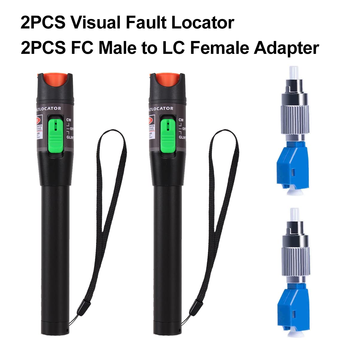
- Visual Fault Locator Pen x 2
- FC Male to LC Female Adapter x 2
- Carrying Bag x 2
- Lanyard x 2
- User Guide x 2
3. Specifications
| Feature | Description |
|---|---|
| Shell Material | Aluminum Alloy (Pen Type) |
| Fiber Optic Adapter | Universal 2.5mm Connector (ST, SC, FC compatible), FC Male to LC Female Adapter included |
| Operating Temperature | 0°C to 60°C (32°F to 140°F) |
| Storage Temperature | -20°C to 70°C (-4°F to 158°F) |
| Dimensions | 175 x 26 x 26 mm (6.89 x 1.02 x 1.02 inches) |
| Product Weight | Approximately 330g (7.83 ounces per unit) |
| Working Mode | Continuous Wave (CW) and Pulse Mode |
| Output Wavelength | 650nm |
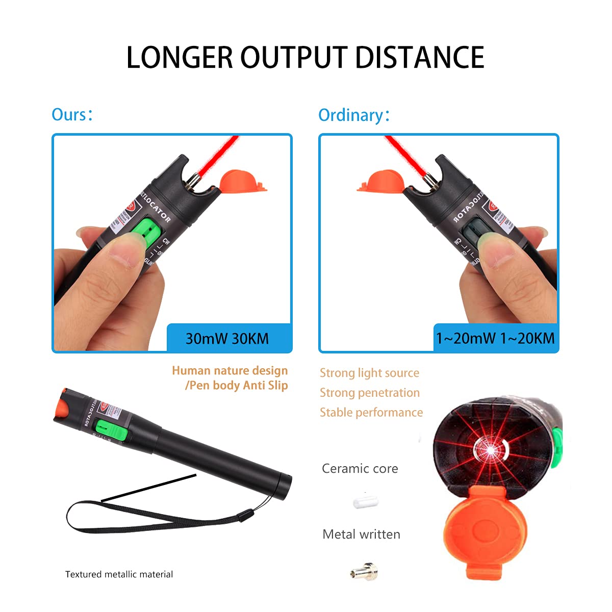
| Output Power | ≥30mW |
| Power Source | 2 x AA Batteries (not included) |
| Output Distance | 20-30 kilometers |


4. Setup
4.1 Battery Installation
- Unscrew the battery cover from the rear end of the Visual Fault Locator.
- Insert two (2) AA batteries into the battery compartment, ensuring correct polarity (+/-).
- Screw the battery cover back on securely.

4.2 Attaching the Lanyard
Thread the provided lanyard through the designated loop on the Visual Fault Locator for convenient carrying and to prevent accidental drops.
5. Operating Instructions
5.1 Connecting to Fiber Optic Cables
- Remove the dust cap from the VFL's output port.
- Clean the fiber optic connector end-face and the VFL's output port with a fiber cleaning tool or lint-free wipe.
- Insert the fiber optic cable connector (ST, SC, or FC) directly into the VFL's 2.5mm universal connector.
- For LC connectors, attach the provided FC Male to LC Female adapter to the VFL, then insert the LC connector into the adapter.
5.2 Operating Modes
The VFL features a slide switch with three positions:
- OFF: Powers off the device.
- CW (Continuous Wave): Provides a steady, continuous red laser light output. This mode is suitable for general fault location and continuity checks.
- PULSE: Provides a pulsed (flashing) red laser light output. This mode can be useful for easier identification of faults over longer distances or in bright environments.
Slide the switch to the desired operating mode (CW or PULSE) to activate the laser.

5.3 Identifying Fiber Faults
Once connected and activated, the VFL will emit a strong 650nm red light into the fiber. Observe the fiber along its path:
- If there is a break, crack, or severe bend in the fiber, the red light will escape from the fiber at that point, making the fault visible.
- Poor connections or dirty end-faces may also cause light leakage or a significant reduction in light intensity at the receiving end.
- The VFL can detect faults over distances of 20-30 kilometers, depending on the fiber quality and fault severity.
6. Maintenance
6.1 Cleaning
- Always keep the fiber optic connector end-faces and the VFL's output port clean. Use specialized fiber optic cleaning tools or lint-free wipes with isopropyl alcohol.
- Regularly clean the exterior of the VFL with a soft, dry cloth. Avoid using abrasive cleaners or solvents.
6.2 Storage
- Always replace the dust cap on the VFL's output port when not in use to prevent dust and debris from entering.
- Store the VFL in its carrying bag to protect it from physical damage and environmental elements.
- Remove batteries if the device will not be used for an extended period to prevent battery leakage.
- Store the device in a dry environment within the specified storage temperature range (-20°C to 70°C).

7. Troubleshooting
| Problem | Possible Cause | Solution |
|---|---|---|
| No light output | 1. Batteries are dead or incorrectly installed. 2. Device is switched to OFF. 3. Output port is blocked. | 1. Replace batteries, ensuring correct polarity. 2. Slide switch to CW or PULSE mode. 3. Remove dust cap and check for obstructions. |
| Weak or intermittent light | 1. Low battery power. 2. Dirty fiber end-face or VFL output port. 3. Loose connection. | 1. Replace batteries. 2. Clean fiber end-face and VFL output port. 3. Ensure fiber connector is securely inserted. |
| Cannot locate fault | 1. Fault is too minor or far away. 2. Fiber is heavily jacketed, obscuring light leakage. 3. Ambient light is too bright. | 1. Ensure VFL is in PULSE mode for better visibility. 2. Inspect fiber in a darker environment. 3. Consider using a higher power VFL for very long distances (this model is 30KM). |
8. Safety Information
This device emits a Class II laser. Observe the following safety precautions:
- DO NOT stare directly into the laser beam.
- DO NOT point the laser at people or animals.
- Avoid direct exposure to the laser beam.
- Use of controls or adjustments or performance of procedures other than those specified herein may result in hazardous radiation exposure.
- Keep out of reach of children.
9. Warranty and Support
VFLTOOL is committed to providing high-quality products and customer satisfaction. This product comes with a quality assurance backed by 10 years of professional production capacity and technical support.
If you experience any dissatisfaction with your purchase, please contact us directly. We offer a return or exchange policy without requiring a specific reason. Your feedback is important to us.
For support or inquiries, please refer to the contact information provided with your purchase or visit the official VFLTOOL store page.