1. Introduction
This manual provides essential information for the proper setup, operation, and maintenance of the JESSINIE LM358 Operational Amplifier Module. This module is designed for weak signal acquisition and amplification, offering up to 100 times adjustable gain. Please read these instructions carefully before use to ensure optimal performance and safety.
2. Product Features
- Dual Operational Amplifiers: Integrates two independent, high-gain, internal frequency compensated operational amplifiers.
- Wide Power Supply Range: Supports single power supply (3V to 30V DC) and dual power supply (±1.5V to ±15V).
- High Gain Bandwidth: Features a unity gain frequency bandwidth of approximately 1MHz and high DC voltage gain (around 100dB).
- Low Power Consumption: Designed for low current consumption, suitable for battery-powered applications.
- Wide Input Voltage Range: Offers a wide common mode input voltage range, including ground, and a differential mode input voltage range equal to the power supply voltage range.
- Large Output Voltage Swing: Provides a large output voltage swing (0 to Vcc-1.5V).
3. Specifications
| Parameter | Value |
|---|---|
| Model | LM358 |
| Minimum Supply Voltage | 3V DC |
| Maximum Supply Voltage | 30V DC |
| Number of Channels | 2 |
| Gain | Adjustable, up to 100 times |
| Mounting Type | Surface Mount |
| Material | Silicon, Plastic/Ceramic |
4. Component Identification
The LM358 Operational Amplifier Module consists of the LM358 IC, passive components, and connection pins. A potentiometer is included for gain adjustment.
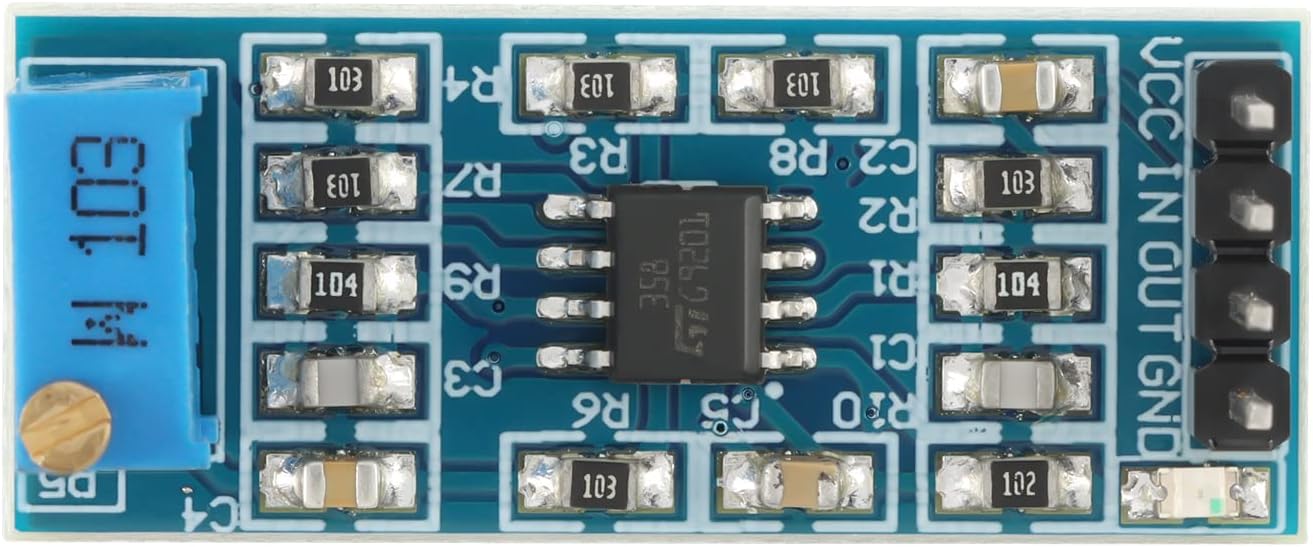
The module features a set of pins for power input, signal input, and signal output. The blue component with a screw is the potentiometer used to adjust the amplification gain.

5. Setup and Connection
Follow these steps to connect the LM358 Operational Amplifier Module:
- Power Supply Connection: Connect your DC power source to the VCC and GND pins. Ensure the voltage is within the specified range of 3V to 30V DC. For dual power supply operation, connect positive voltage to VCC, negative voltage to GND, and the common ground to the appropriate pin (if applicable to your specific setup).
- Signal Input: Connect the weak signal you wish to amplify to the IN pin. The signal should be referenced to the module's ground (GND).
- Signal Output: The amplified signal will be available at the OUT pin. Connect this to your desired load or next stage of your circuit.
- Gain Adjustment: Use a small screwdriver to turn the screw on the blue potentiometer to adjust the amplification gain. Turning clockwise typically increases gain, while counter-clockwise decreases it.
Important Note: This module is primarily designed for AC signal amplification. It does not reliably support the amplification of DC signals. Attempting to amplify DC signals may result in unexpected behavior or inaccurate readings.
6. Operating Instructions
Once connected, apply power to the module. The LM358 will begin amplifying the input signal. Adjust the potentiometer to achieve the desired level of amplification. Monitor the output signal with an oscilloscope or multimeter to verify the amplified waveform and ensure it is within acceptable limits for your application.
The module's high DC voltage gain and unity gain frequency bandwidth make it suitable for a variety of analog signal processing tasks where weak AC signals need to be boosted.
7. Maintenance
The LM358 Operational Amplifier Module requires minimal maintenance. Keep the module clean and free from dust and moisture. Avoid exposing it to extreme temperatures or mechanical stress. Periodically check connections for secure contact.
Handle the potentiometer gently during gain adjustment to prevent damage. Excessive force can lead to component failure.
8. Troubleshooting
- No Output / Incorrect Output:
- Verify power supply connections (VCC, GND) and ensure voltage is within the 3V-30V range.
- Check input signal connection to the IN pin.
- Ensure the potentiometer is not set to minimum gain (zero amplification).
- Confirm the input signal is an AC signal. This module is not designed for DC signal amplification.
- Unstable Output / Noise:
- Ensure proper grounding of the module and your signal source.
- Check for external electromagnetic interference.
- Verify the power supply is stable and free of ripple.
- Potentiometer Issues: If the gain adjustment is erratic or non-responsive, the potentiometer may be faulty. Handle with care to prevent damage.
9. Safety Information
- Always ensure power is disconnected before making or changing connections.
- Do not exceed the maximum specified supply voltage of 30V DC.
- Avoid short-circuiting the output or power supply pins.
- Handle electronic components with care to prevent electrostatic discharge (ESD) damage.
- If you are unsure about any connection or operation, consult a qualified electronics professional.
10. Warranty and Support
For warranty information and technical support, please refer to the product's purchase documentation or contact JESSINIE customer service through the platform where the product was purchased. Please have your product model (LM358) and purchase details ready when contacting support.