1. Introduction
This user manual provides detailed instructions for the safe and effective operation, maintenance, and troubleshooting of the VIHELM ZT-111 Multi-Function Digital Multimeter. Please read this manual thoroughly before using the device to ensure proper functionality and to prevent damage or injury.
2. Safety Information
Always adhere to the following safety precautions to prevent electric shock, fire, or damage to the meter or the equipment under test.
- Do not exceed the maximum input limits for any function.
- Do not use the meter if it or the test leads appear damaged.
- Exercise extreme caution when working with voltages above 30V AC RMS, 42V peak, or 60V DC. These voltages pose a shock hazard.
- Always disconnect the test leads from the circuit before changing functions or ranges.
- Ensure the correct function and range are selected for the measurement.
- Keep fingers behind the finger guards on the test leads during measurements.
- Replace the battery as soon as the low battery indicator appears to ensure accurate readings.
3. Package Contents
Verify that all items listed below are present in your package:
- ZT-111 Digital Multimeter (1 unit)
- Test Leads (1 pair)
- User Manual (This document)
4. Product Overview
The VIHELM ZT-111 is a compact, multi-functional digital multimeter designed for various electrical measurements. It features a clear digital display, a rotary function switch, and multiple input jacks.

Figure 4.1: Front view of the ZT-111 Digital Multimeter, showing the display, rotary dial, and input terminals.
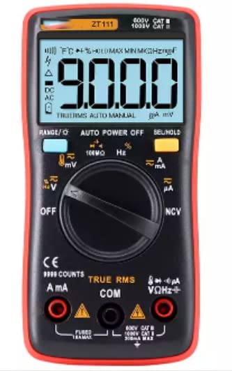
Figure 4.2: Close-up view of the ZT-111's digital display and the central rotary switch, highlighting various measurement functions like voltage, current, resistance, and frequency.

Figure 4.3: Rear view of the ZT-111 Digital Multimeter, showing the battery compartment cover and product labeling.
Figure 4.4: Rear view of the ZT-111 Digital Multimeter with its integrated kickstand extended, allowing for angled viewing on a flat surface.
5. Setup
5.1 Battery Installation
The ZT-111 multimeter is powered by AAA batteries. To install or replace batteries:
- Ensure the multimeter is turned OFF and test leads are disconnected.
- Locate the battery compartment on the rear of the device (refer to Figure 4.3).
- Unscrew the retaining screw(s) and remove the battery cover.
- Insert the AAA batteries, observing the correct polarity (+ and -).
- Replace the battery cover and secure it with the screw(s).
5.2 Connecting Test Leads
Connect the test leads to the appropriate input jacks on the multimeter:
- Insert the black test lead into the COM (Common) jack.
- For most voltage, resistance, frequency, capacitance, and diode measurements, insert the red test lead into the VΩHz+ jack.
- For current measurements (mA/A), insert the red test lead into the mA/A or μA jack, depending on the expected current range.
6. Operation
The ZT-111 offers a wide range of measurement functions. Turn the rotary switch to select the desired function.
6.1 DC Voltage Measurement (V–)
To measure DC voltage:
- Set the rotary switch to the V– position.
- Connect the red test lead to the positive (+) side of the circuit and the black test lead to the negative (-) side.
- Read the voltage value on the display.
6.2 AC Voltage Measurement (V~)
To measure AC voltage:
- Set the rotary switch to the V~ position.
- Connect the test leads across the AC voltage source.
- Read the voltage value on the display.
6.3 Current Measurement (A– / A~)
To measure DC or AC current:
- Set the rotary switch to the appropriate A– (DC) or A~ (AC) position (e.g., mA, A, μA).
- Important: Disconnect power to the circuit. Open the circuit where current is to be measured.
- Connect the multimeter in series with the circuit. The current must flow through the multimeter.
- Apply power to the circuit and read the current value.
6.4 Resistance Measurement (Ω)
To measure resistance:
- Set the rotary switch to the Ω position.
- Ensure the circuit is de-energized before measuring resistance.
- Connect the test leads across the component to be measured.
- Read the resistance value on the display.
6.5 Non-Contact Voltage (NCV) Detection
The ZT-111 features NCV detection for identifying live AC voltage without direct contact.
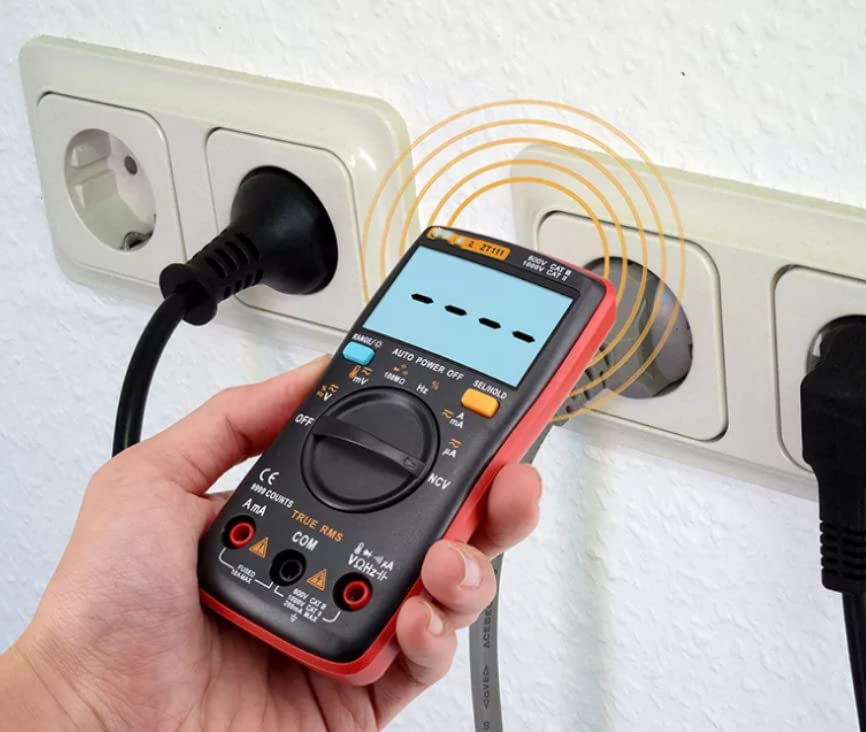
Figure 6.1: Demonstrating Non-Contact Voltage (NCV) detection with the ZT-111 multimeter near an electrical outlet. The display shows a signal indicating voltage presence.
- Set the rotary switch to the NCV position.
- Move the top part of the multimeter (where the NCV sensor is located) close to the wire or outlet you want to test.
- The meter will emit an audible beep and/or display a visual indication (e.g., bars on the screen) if AC voltage is detected.
6.6 Other Functions
- Capacitance (F): Measure capacitance by setting the switch to the capacitance range and connecting leads across the capacitor (ensure it's discharged).
- Frequency (Hz) / Duty Ratio (%): Measure frequency and duty cycle by setting the switch to the Hz/% position.
- Temperature (°C/°F): Use a K-type thermocouple (not included) and set the switch to the temperature position.
- Diode/Continuity Test: Set the switch to the diode/continuity position. Use for testing diodes or checking for circuit continuity (audible beep for continuity).
- True RMS: The ZT-111 features True RMS measurement for accurate readings on non-sinusoidal AC waveforms.
- Auto Power Off: The meter will automatically power off after a period of inactivity to conserve battery life.
- Data Hold (SEL/HOLD): Press the HOLD button to freeze the current reading on the display. Press again to release.
7. Specifications
The following table provides detailed technical specifications for the VIHELM ZT-111 Digital Multimeter:
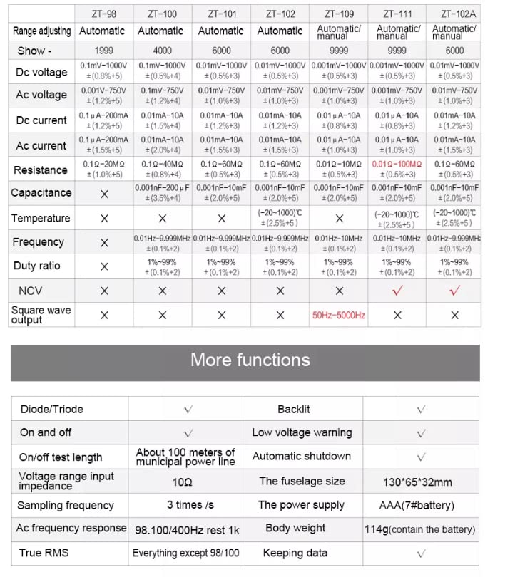
Figure 7.1: A detailed comparison table outlining the specifications and features of various ZT series multimeters, with the ZT-111 column providing specific technical data for this model.
| Parameter | ZT-111 Specification |
|---|---|
| Display Count | 9999 Counts |
| DC Voltage Range | 0.001mV - 1000V (±(1.0%+3)) |
| AC Voltage Range | 0.001mV - 750V (±(1.0%+3)) |
| DC Current Range | 0.01mA - 10A (±(1.2%+3)) |
| AC Current Range | 0.01mA - 10A (±(1.5%+3)) |
| Resistance Range | 0.1Ω - 100MΩ (±(0.5%+3)) |
| Capacitance Range | 0.001nF - 100mF (±(2.0%+5)) |
| Temperature Range | -20°C - 1000°C (±(2.5%+5)) |
| Frequency Range | 0.01Hz - 10MHz (±(0.1%+2)) |
| Duty Ratio | 1% - 99% (±(0.1%+2)) |
| NCV | Yes |
| Diode/Triode Test | Yes |
| On/Off Test Length | About 100 meters of municipal power line |
| Voltage Range Input Impedance | 10MΩ |
| Sampling Frequency | 3 times/s |
| AC Frequency Response | 98.100/400Hz rest 1K |
| True RMS | Yes |
| Backlit | Yes |
| Low Voltage Warning | Yes |
| Automatic Shutdown | Yes |
| Fuselage Size (L x W x H) | 130 x 65 x 32 mm |
| Power Supply | AAA (7# battery) |
| Body Weight (with battery) | 114g |
| Data Keeping | Yes |
Note: Specifications are subject to change without notice for product improvement.
8. Maintenance and Care
8.1 Cleaning
To clean the multimeter, use a soft cloth dampened with mild detergent. Do not use abrasives or solvents. Ensure the device is powered off and disconnected from any circuits before cleaning.
8.2 Battery Replacement
When the low battery indicator appears on the display, replace the batteries promptly to ensure accurate measurements. Refer to Section 5.1 for battery installation instructions.
8.3 Storage
If the multimeter is not used for an extended period, remove the batteries to prevent leakage and corrosion. Store the device in a cool, dry place, away from direct sunlight and extreme temperatures.
9. Troubleshooting
If you encounter issues with your ZT-111 multimeter, refer to the following common problems and solutions:
| Problem | Possible Cause | Solution |
|---|---|---|
| No display or dim display | Dead or low batteries | Replace batteries (refer to Section 5.1). |
| Incorrect readings | Incorrect function/range selected; Poor test lead connection; Damaged test leads; Overload condition | Verify function and range; Ensure leads are securely connected; Inspect and replace damaged leads; Check input limits. |
| Meter does not respond | Auto power off activated; Internal fuse blown (for current measurements) | Turn the rotary switch to OFF and then back ON; Check and replace fuse if necessary (consult qualified technician). |
If the problem persists after trying these solutions, please contact customer support.
10. Warranty and Support
This product is subject to the return policy of the retailer from which it was purchased. For the VIHELM ZT-111, a 30-day return period is typically offered from the date of purchase. Please refer to your purchase documentation or the retailer's website for specific warranty terms and conditions.
For technical support or inquiries, please contact the seller or manufacturer directly through the platform where the product was acquired.