
Introduction
This manual provides comprehensive instructions for the proper setup, operation, and maintenance of your FMS MG41 + R4A RC Transmitter and Receiver Set. Please read this manual thoroughly before using the product to ensure safe and optimal performance. This set is designed for use with FMS 1:12 Land Rover, 1:12 FJ45, 1:12 JIMNY, and 1:18 Apache RC vehicles.
Package Contents
Verify that all items listed below are included in your package:
- Transmitter (MG41)
- Receiver (R4A)
Product Overview
Familiarize yourself with the components of your FMS MG41 Transmitter and R4A Receiver.
Transmitter Layout
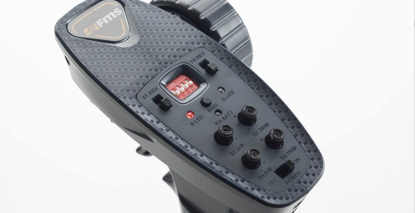
Image: Top-down view of the FMS MG41 RC Transmitter, highlighting the steering wheel, throttle trigger, and various control buttons and switches on the top panel.
The transmitter features a pistol-grip design with a steering wheel for directional control and a trigger for throttle. The top panel includes several controls and indicators:
- ST.REV (Steering Reverse Switch): Reverses the steering direction.
- TH.REV (Throttle Reverse Switch): Reverses the throttle direction.
- R.LED (Red LED): Indicates transmitter status, often related to power or binding.
- BIND Button: Used for pairing the transmitter with the receiver.
- G.LED (Green LED): Indicates successful binding and operational status.
- RX.BATT (Receiver Battery Indicator): Shows the receiver's battery status.
- ST.D/R (Steering Dual Rate Knob): Adjusts the maximum steering angle.
- ST.TRIM (Steering Trim Knob): Adjusts the neutral position of the steering.
- TH.D/R (Throttle Dual Rate Knob): Adjusts the maximum throttle output.
- TH.TRIM (Throttle Trim Knob): Adjusts the neutral position of the throttle.
- POWER Switch: Turns the transmitter on or off.
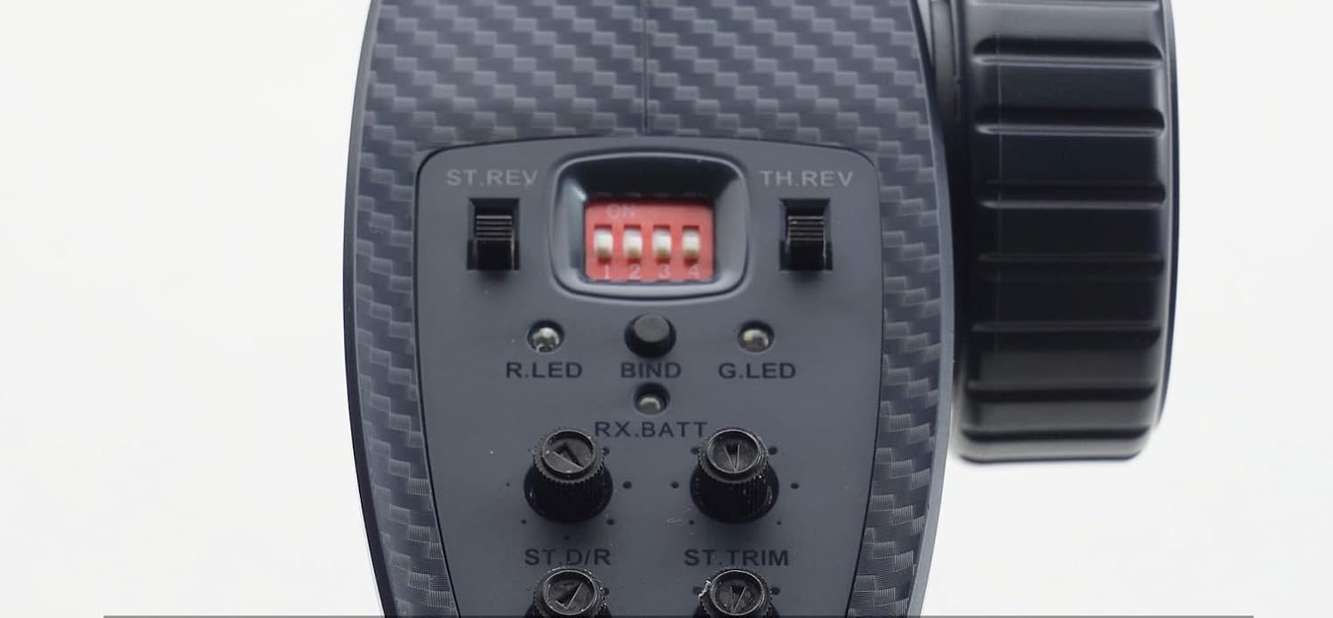
Image: Close-up view of the FMS MG41 RC Transmitter's dip switches (1-4) located on the top panel, used for advanced function settings.
The transmitter also includes a set of Dip Switches (1-4) for advanced function settings. These switches configure various vehicle behaviors, such as brake settings or other specific functions depending on the RC vehicle model.
Receiver Overview

Image: The FMS R4A RC Receiver module, a small circuit board with attached wires for connection to the RC vehicle's electronic speed controller (ESC) and other components.
The R4A receiver is a compact unit designed to receive signals from the MG41 transmitter and relay them to the vehicle's electronic components (ESC, servo, lights, etc.). It features multiple ports for connecting various components.
Setup
1. Battery Installation (Transmitter)
- Open the battery compartment cover on the bottom of the transmitter.
- Insert the required batteries (typically AA, refer to the battery compartment for specifics) ensuring correct polarity.
- Close the battery compartment cover securely.
2. Binding the Transmitter and Receiver
If your transmitter and receiver are not already bound, follow these steps to establish a connection:
- Ensure the RC vehicle's power is OFF.
- On the transmitter, press and hold the BIND button.
- While holding the BIND button, turn the POWER switch on the transmitter to the ON position. The Red LED (R.LED) should illuminate, and the Green LED (G.LED) should start flashing, indicating "BIND MODE".
- Whilst the Green LED on the transmitter is flashing, turn on the RC vehicle's power.
- Successful binding is indicated when the Green LED on the transmitter stops flashing and remains solid.
- Release the BIND button.
Video: This video demonstrates the binding process for the FMS MG41 + R4A Transmitter and Receiver Set, showing how to put the transmitter into bind mode and connect it to the vehicle's receiver.
Operating Instructions
Basic Controls
- Steering: Turn the steering wheel left or right to control the vehicle's direction.
- Throttle: Pull the trigger towards you to move forward. Push the trigger away from you to brake or reverse.
Advanced Settings (Dip Switches)
The dip switches on the transmitter allow for customization of vehicle behavior. Refer to your specific RC vehicle's manual for detailed configurations. For example:
- Switch #1 (Vehicle Brake Switch): This switch controls the vehicle's braking behavior.
- Position 1 (ON): Allows the vehicle to reverse directly when moving from forward to reverse on the controller (no brake).
- Position 2 (OFF): Applies the brake first, then allows reverse.
- Other dip switches may control functions like steering sensitivity, throttle curves, or auxiliary channels depending on the vehicle model. Always consult your vehicle's specific instructions.
Additional Controls (Side Panel)

Image: Side view of the FMS MG41 RC Transmitter, indicating the location of the gear setting button and the light switch button.
- Gear Setting Button: Located on the right side of the remote control. This button can be used to switch between different gear modes, such as climbing mode and high-speed mode, if supported by your vehicle.
- Light Switch Button: Also on the right side. This controls the vehicle's lighting, typically toggling between low beam and high beam, or turning lights on/off.
Maintenance
- Cleaning: Use a soft, dry cloth to clean the transmitter and receiver. Avoid using solvents or harsh chemicals.
- Storage: Store the unit in a cool, dry place away from direct sunlight and extreme temperatures. Remove batteries from the transmitter if storing for extended periods to prevent leakage.
- Battery Care: Always use fresh batteries of the recommended type. Do not mix old and new batteries or different battery types.
- Connection Checks: Periodically inspect all wiring and connections for signs of wear or damage.
Troubleshooting
| Problem | Possible Cause | Solution |
|---|---|---|
| No power to transmitter | Dead or incorrectly installed batteries. | Replace batteries with fresh ones, ensuring correct polarity. |
| Vehicle not responding | Not bound, out of range, or receiver power issue. | Perform binding procedure. Ensure vehicle and transmitter are powered on and within range. Check receiver connections. |
| Erratic control | Interference, loose connections, or trim settings. | Move to an area with less interference. Check all wiring. Adjust ST.TRIM and TH.TRIM. |
| Steering/Throttle reversed | ST.REV or TH.REV switch incorrectly set. | Toggle the corresponding reverse switch (ST.REV or TH.REV) to the correct position. |
Specifications
- Model: C2131-MG41 (Transmitter) + R4A (Receiver)
- Package Dimensions: 6.61 x 5.63 x 3.19 inches
- Item Weight: 5.3 ounces
- Manufacturer: Fms Model
- Recommended Age: 14 years and up
- Compatibility: FMS 1:12 Land Rover, 1:12 FJ45, 1:12 JIMNY, 1:18 Apache RC cars.
Warranty and Support
For warranty information and technical support, please refer to the official FAIR RC website or contact their customer service directly. Details regarding specific warranty periods and support procedures are typically provided with your purchase documentation or on the manufacturer's website.
If you encounter any issues not covered in this manual, please reach out to the manufacturer's support team for assistance.