1. Introduction
This manual provides detailed instructions for the proper use and integration of the Import brand XL2001E1 XL2001 DC-DC Converter Integrated Circuit (IC). The XL2001 is a high-efficiency, step-down DC-DC converter, designed to provide a stable output voltage from a higher input voltage. It is supplied in an SOP-8 package, making it suitable for various compact electronic applications.
2. Key Features
- Wide Input Voltage Range: Typically 3.6V to 18V.
- Adjustable Output Voltage: Down to 0.8V.
- High Efficiency: Optimized for power conversion.
- Integrated Power MOSFET: Reduces external component count.
- Fixed Switching Frequency: Typically 150kHz or 300kHz.
- Built-in Protection Functions: Over-current protection (OCP) and thermal shutdown (TSD).
- SOP-8 Package: Standard surface-mount package for ease of integration.
3. Typical Applications
- Distributed Power Systems
- Battery Chargers
- Pre-regulator for Linear Regulators
- Set-top Boxes
- LCD Televisions
- General Purpose DC-DC Conversion
4. Pin Configuration and Description
The XL2001E1/XL2001 is housed in an SOP-8 package. The following table and diagram illustrate a typical pin configuration and their functions. Refer to the specific datasheet for the exact pinout of your component.

Figure 1: Top-down view of the XL2001E1 XL2001 SOP-8 integrated circuit, showing its markings and eight pins.
| Pin No. | Name | Description |
|---|---|---|
| 1 | SW | Switch Output. Connect to the inductor. |
| 2 | GND | Ground. |
| 3 | FB | Feedback Pin. Connect to the output voltage divider. |
| 4 | EN | Enable Pin. High to enable, Low to disable. |
| 5 | VIN | Input Voltage. |
| 6 | VIN | Input Voltage. |
| 7 | NC | No Connect. |
| 8 | NC | No Connect. |
5. Setup and Integration
Integrating the XL2001E1/XL2001 into a circuit requires careful consideration of external components and layout.
5.1. Essential External Components
- Input Capacitor (CIN): A low ESR ceramic capacitor (e.g., 10µF to 47µF) is recommended at the VIN pin to reduce input voltage ripple and supply transient current. Place it as close as possible to the VIN and GND pins.
- Output Capacitor (COUT): A low ESR ceramic capacitor (e.g., 22µF to 100µF) is required at the output to filter the output voltage and provide stability.
- Inductor (L): Select an inductor with appropriate inductance (e.g., 10µH to 47µH) and saturation current rating to handle the peak inductor current.
- Feedback Resistors (R1, R2): Two resistors form a voltage divider to set the output voltage. Connect R1 from VOUT to FB, and R2 from FB to GND. The output voltage (VOUT) can be calculated using the formula: VOUT = VFB * (1 + R1/R2), where VFB is the internal feedback voltage (typically 0.8V).
- Diode (D): A Schottky diode is typically used as the freewheeling diode, connected between SW and GND.
5.2. PCB Layout Guidelines
- Keep the power traces (VIN, SW, VOUT, GND) as short and wide as possible to minimize parasitic inductance and resistance.
- Place the input capacitor, output capacitor, and inductor close to the IC.
- Ensure a solid ground plane for optimal thermal performance and noise reduction.
- Route the feedback trace (from VOUT to FB pin) away from noisy switching nodes (SW pin) to prevent interference.
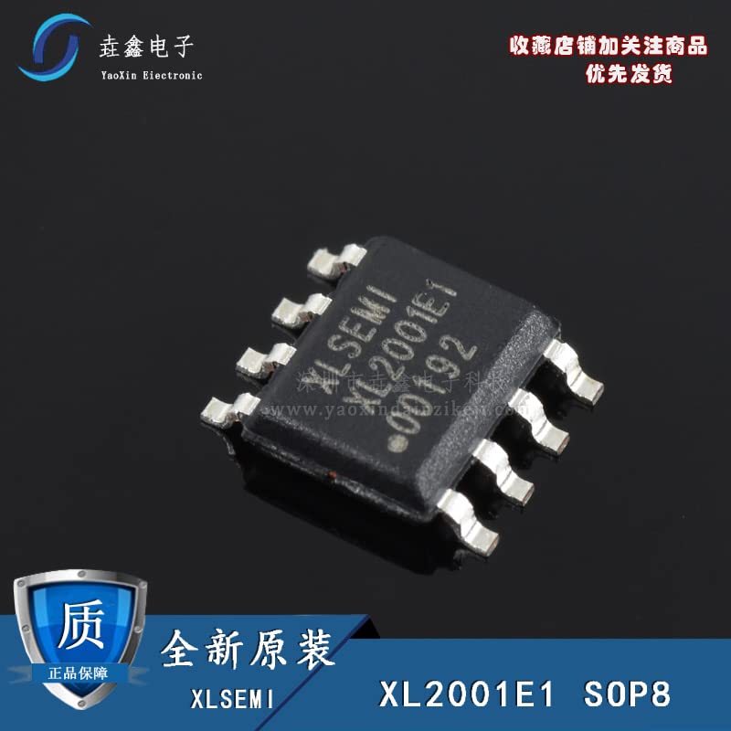
Figure 2: A close-up view of the XL2001E1 XL2001 IC, showing package details and pin leads. Chinese text is visible on the image.
6. Operating Instructions
Once the XL2001E1/XL2001 is correctly integrated into your circuit, follow these general operating guidelines:
- Input Power: Apply the input voltage (VIN) within the specified range (e.g., 3.6V to 18V) to the VIN pins. Ensure the power supply can deliver the required current.
- Enable Pin (EN): To enable the converter, apply a voltage above the logic high threshold (e.g., >1.5V) to the EN pin. To disable, pull the EN pin low (e.g., <0.5V) or connect it to GND.
- Output Voltage Adjustment: The output voltage is set by the feedback resistor divider (R1 and R2). Adjust these resistor values to achieve the desired output voltage.
- Load Connection: Connect your load to the VOUT and GND terminals. Ensure the load current does not exceed the maximum output current rating of the XL2001 (e.g., 1.5A or 2A).
- Monitoring: Monitor the output voltage and current to ensure stable operation and adherence to design specifications.
7. Maintenance and Handling
The XL2001E1/XL2001 is a robust integrated circuit, but proper handling and maintenance practices are essential for its longevity and reliable operation.
- Storage: Store ICs in their original anti-static packaging in a dry, temperature-controlled environment to prevent moisture absorption and electrostatic discharge (ESD) damage.
- Handling: Always use ESD-safe practices when handling the IC, including wearing anti-static wrist straps and working on an ESD-protected surface. Avoid touching the pins directly.
- Soldering: Follow recommended soldering profiles to prevent thermal stress to the component. Avoid excessive heat or prolonged exposure to high temperatures.
- Cleaning: If cleaning is necessary, use appropriate electronic-grade cleaning agents and ensure the component is completely dry before powering on.
- Inspection: Periodically inspect the soldered connections and surrounding components for any signs of damage, corrosion, or cold solder joints.
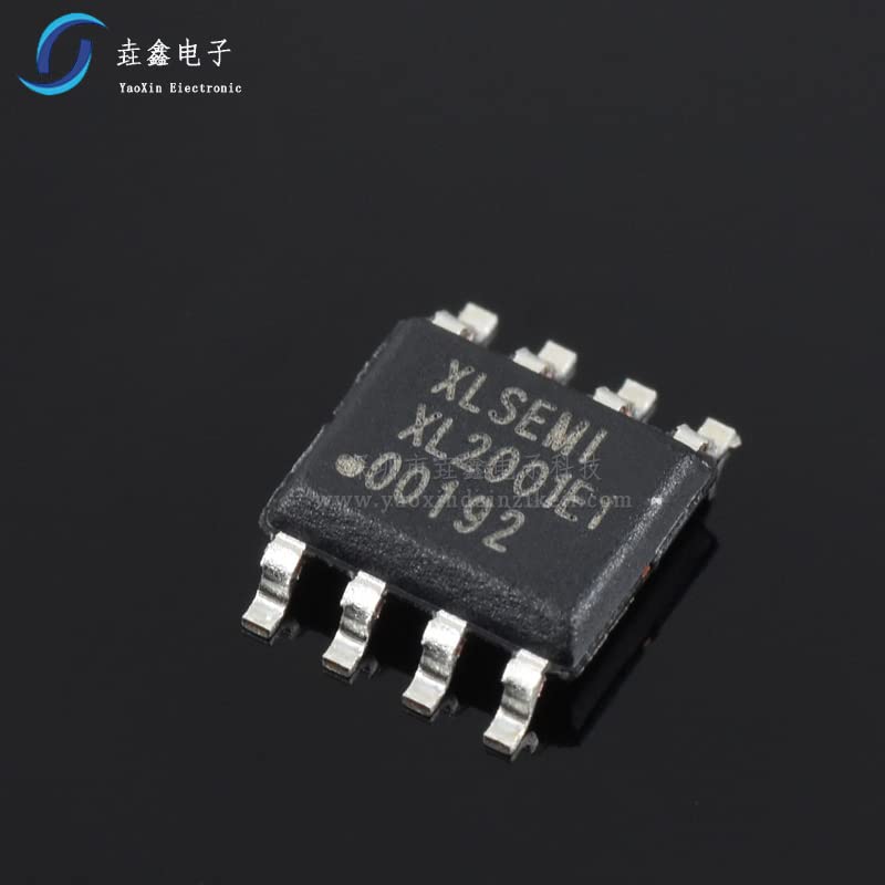
Figure 3: An angled view of the XL2001E1 XL2001 IC, highlighting the SOP-8 package and its metallic leads.
8. Troubleshooting
If you encounter issues with the XL2001E1/XL2001, consider the following common troubleshooting steps:
- No Output Voltage:
- Verify input voltage (VIN) is present and within the specified range.
- Check the Enable (EN) pin status. Ensure it is pulled high.
- Inspect for short circuits on the output.
- Confirm correct component placement and soldering.
- Incorrect Output Voltage:
- Verify the values of the feedback resistors (R1, R2) and their connections.
- Check for excessive load current exceeding the IC's capabilities.
- Inspect for poor grounding or noisy feedback traces.
- Output Ripple/Noise:
- Ensure input and output capacitors have low ESR and are correctly sized and placed.
- Check for proper PCB layout, especially short and wide power paths and a solid ground plane.
- Verify the inductor is correctly sized and has sufficient current rating.
- Overheating:
- Ensure the load current does not exceed the maximum rating.
- Check for adequate thermal dissipation on the PCB.
- Verify input voltage is not excessively high, leading to higher power dissipation.
9. Technical Specifications
The following are typical specifications for the XL2001E1/XL2001. Always refer to the manufacturer's official datasheet for precise and guaranteed parameters.
| Parameter | Value | Unit |
|---|---|---|
| Input Voltage Range (VIN) | 3.6 to 18 | V |
| Output Voltage Range (VOUT) | 0.8 to VIN | V |
| Maximum Output Current | 1.5 (typical) | A |
| Switching Frequency | 150 (typical) | kHz |
| Feedback Voltage (VFB) | 0.8 (typical) | V |
| Operating Junction Temperature | -40 to +125 | °C |
| Package Type | SOP-8 | - |
10. Warranty and Support
This product is supplied by Import brand. For specific warranty information, please refer to the terms and conditions provided by your point of purchase or the seller, Shenzhen yuzhiyuanxin Electronics Co., Ltd. General product quality is assured, and the seller emphasizes strict quality control and authentic components.
For technical support or inquiries regarding the XL2001E1/XL2001, it is recommended to consult the official datasheet from the IC manufacturer or contact your component supplier directly. Ensure you have the full model number and any relevant batch codes when seeking support.