1. Introduction
The UNI-T UT18E is a robust RCD handheld digital multimeter designed for testing AC/DC voltage, 3-phase voltage, phase sequence, and continuity. This device is categorized as CAT IV 600V and meets IP65 standard, making it suitable for electricians to quickly measure voltage levels in various electrical systems, including those with 110V electrical systems.
Key features include RCD testing, polarity detection, auto-inspection, automatic standby mode, silent mode, work light, and low battery indication.
2. Safety Information
WARNING: Before using the UNI-T UT18E, please read and understand all safety information and operating instructions in this manual. Failure to do so may result in electric shock, injury, or damage to the meter or equipment under test.
- Always verify the meter's operation on a known voltage source before use.
- Do not use the meter if it appears damaged or if the test leads are damaged.
- Observe all local and national safety codes.
- Do not apply more than the rated voltage, as marked on the meter, between the terminals or between any terminal and ground.
- Use extreme caution when working with voltages above 30V AC RMS, 42V peak, or 60V DC. Such voltages pose a shock hazard.
- Keep fingers behind the finger guards on the test probes during use.
- Replace the battery immediately when the low battery indicator appears to ensure accurate readings.
- The device is certified CE, UKCA, and cETLus, and rated CAT IV 600V, CAT III 690V.
3. Product Overview and Components
Familiarize yourself with the components of your UNI-T UT18E multimeter.

Figure 3.1: Labeled components of the UNI-T UT18E Voltage and Continuity Tester. Key parts include Test Pen Caps, Test Pens L1 and L2, High-Voltage Indication, AC Indication, Voltage Indication, Continuity Indication, RCD Indication, Rotary Phase Indication, Polar Indication, LCD Display, RDC Test Button, Flashlight/Self-Inspection Button, Hold Mode/Backlight Button, and Battery Cover.
The device features an LCD display for clear readings and LED indicators for various functions. It is designed with an IP65 waterproof rating for durability in various environments.

Figure 3.2: Overview of UNI-T UT18E features, including IP65 waterproof rating, LCD display, continuity test with buzzer and LED indication, auto range/inspection, auto power off, continuity, phase sequence, 3-phase voltage, and AC/DC measurement capabilities.
4. Setup and Battery Installation
The UNI-T UT18E is powered by batteries. Ensure batteries are correctly installed before first use.
4.1 Battery Installation
- Locate the battery cover on the back of the device (refer to Figure 3.1).
- Use a suitable screwdriver to open the battery compartment.
- Insert the required batteries, observing the correct polarity (+ and -). The device typically uses 1.5V AAA batteries (3x).
- Replace the battery cover and secure it with the screw.
The package includes batteries and test leads, so your device should be ready for initial setup.
5. Operating Instructions
The UT18E offers various measurement functions. Always ensure the test leads are securely connected and the device is in good working condition before performing any tests.
5.1 Voltage Measurement (AC/DC)
- Connect the test leads to the circuit or component to be measured.
- The device will automatically detect AC or DC voltage and display the reading on the LCD.
- Voltage indication LEDs will illuminate to show approximate voltage levels (12V, 24V, 50V, 120V, 230V, 400V, 690V).
- The device supports voltage measurements up to 690V.
5.2 Continuity Test
- Connect the test leads across the circuit or component to check for continuity.
- If continuity is detected, the device will emit a buzzer sound and an LED indicator will illuminate.
5.3 RCD Test
The RCD (Residual Current Device) test function verifies the proper operation of RCDs.
- Connect the test leads to the circuit protected by an RCD.
- Press the RDC Test Button (refer to Figure 3.1).
- The RCD should trip, indicating correct functionality. The operating voltage for RCD test is 230V/50Hz ~ 400Hz.
5.4 Phase Sequence Test (3-Phase Voltage)
This function is used to determine the phase sequence in 3-phase electrical systems.
- Connect the test leads to the three phases of the system.
- The device will indicate the phase sequence (e.g., L1, L2, L3) on the display or via specific indicators.
5.5 Polarity Detection
The UT18E automatically detects and indicates the polarity (positive and negative) of DC voltage.
5.6 Auto-Inspection and Flashlight
- Auto-Inspection: The device performs a self-inspection, illuminating all LEDs or LCD segments to confirm proper function. This can be initiated via the Flashlight/Self-Inspection Button.
- Flashlight: Press the Flashlight/Self-Inspection Button to activate the built-in work light for illumination in dark environments.

Figure 5.1: The integrated flashlight provides illumination for working in low-light conditions.
5.7 Hold Mode and Backlight
Press the Hold Mode/Backlight Button to freeze the current reading on the display or to activate the LCD backlight for better visibility.
6. Maintenance
Proper maintenance ensures the longevity and accuracy of your UNI-T UT18E multimeter.
6.1 Cleaning
- Wipe the case with a damp cloth and mild detergent. Do not use abrasives or solvents.
- Ensure the device is completely dry before storage or next use.
6.2 Battery Replacement
When the low battery indicator appears (around 2.5V), replace the batteries as described in Section 4.1. Always use new batteries of the specified type.
6.3 Storage
- If the meter is not used for an extended period, remove the batteries to prevent leakage.
- Store the device in a cool, dry place, away from direct sunlight and extreme temperatures.
7. Troubleshooting
If you encounter issues with your UNI-T UT18E, refer to the following common problems and solutions.
| Problem | Possible Cause | Solution |
|---|---|---|
| Device does not power on. | Dead or incorrectly installed batteries. | Check battery polarity and replace batteries if necessary. |
| Inaccurate readings. | Low battery, damaged test leads, or incorrect measurement mode. | Replace batteries, inspect test leads for damage, ensure correct function is selected (though UT18E is auto-ranging for voltage). |
| No continuity indication. | Open circuit, damaged test leads, or low battery. | Verify the circuit is closed, check test leads, replace batteries. |
| RCD test fails to trip. | RCD fault, incorrect connection, or voltage outside operating range. | Ensure proper connection, verify circuit voltage is within 230V-400Hz, consult a qualified electrician if RCD still fails. |
If the problem persists after attempting these solutions, contact customer support. Do not attempt to repair the device yourself.
8. Specifications
Detailed technical specifications for the UNI-T UT18E RCD Handheld Digital Multimeter.

Figure 8.1: Comprehensive specifications for the UNI-T UT18 series, including UT18C and UT18D models. The UT18E shares many of these characteristics.
| Feature | Specification |
|---|---|
| Model Number | UT18E (based on product title, UT18 series) |
| Voltage Range | 12V to 690V AC/DC |
| RCD Test Voltage | 230V/50Hz ~ 400Hz |
| Polarity Detection | Positive and Negative |
| Auto-Inspection | All LED or LCD segments |
| Exceeded Voltage Indication | 713V ~ 788V |
| Auto Standby Current | < 10µA |
| Low Battery Indication | Around 2.5V |
| Power Source | Battery (3x 1.5V AAA, typically) |
| Product Dimensions | 27.2 x 8.5 x 3.1 cm |
| Product Weight | 277 g |
| Certifications | CE, UKCA, cETLus, CAT IV 600V, CAT III 690V, IP65 |
| Included Components | Batteries, Test Leads |
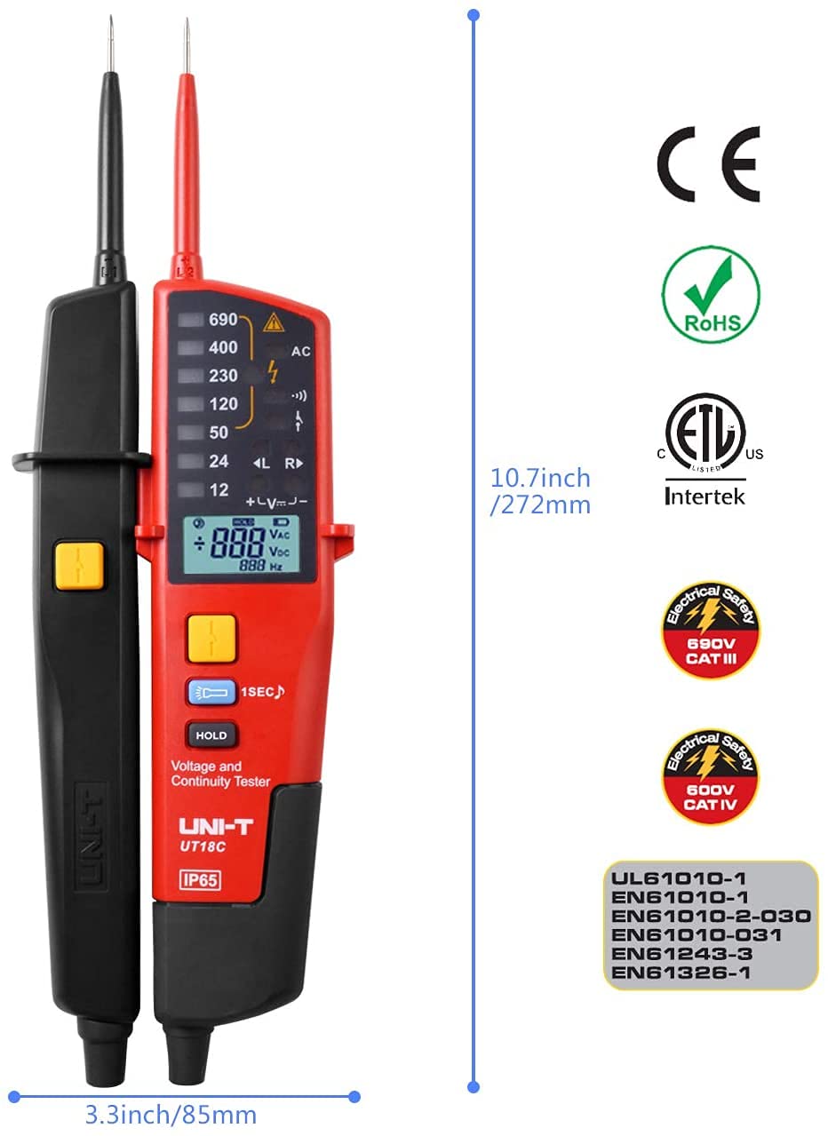
Figure 8.2: Physical dimensions and safety compliance markings for the UNI-T UT18E.
9. Warranty and Support
UNI-T products are manufactured to high-quality standards. For specific warranty terms and conditions, please refer to the warranty card included with your product or visit the official UNI-T website.
For technical support, troubleshooting assistance beyond this manual, or service inquiries, please contact UNI-T customer service through their official channels. Do not attempt to open or repair the device yourself, as this may void the warranty and pose safety risks.


