Introduction
This manual provides detailed instructions for the installation, operation, and maintenance of your GOOD STORY Wireless Bridge Point to Point Outdoor WiFi System, Model WB610H. This system is designed to extend your network wirelessly over long distances, providing a stable and high-speed connection between two or more locations without the need for extensive cabling.
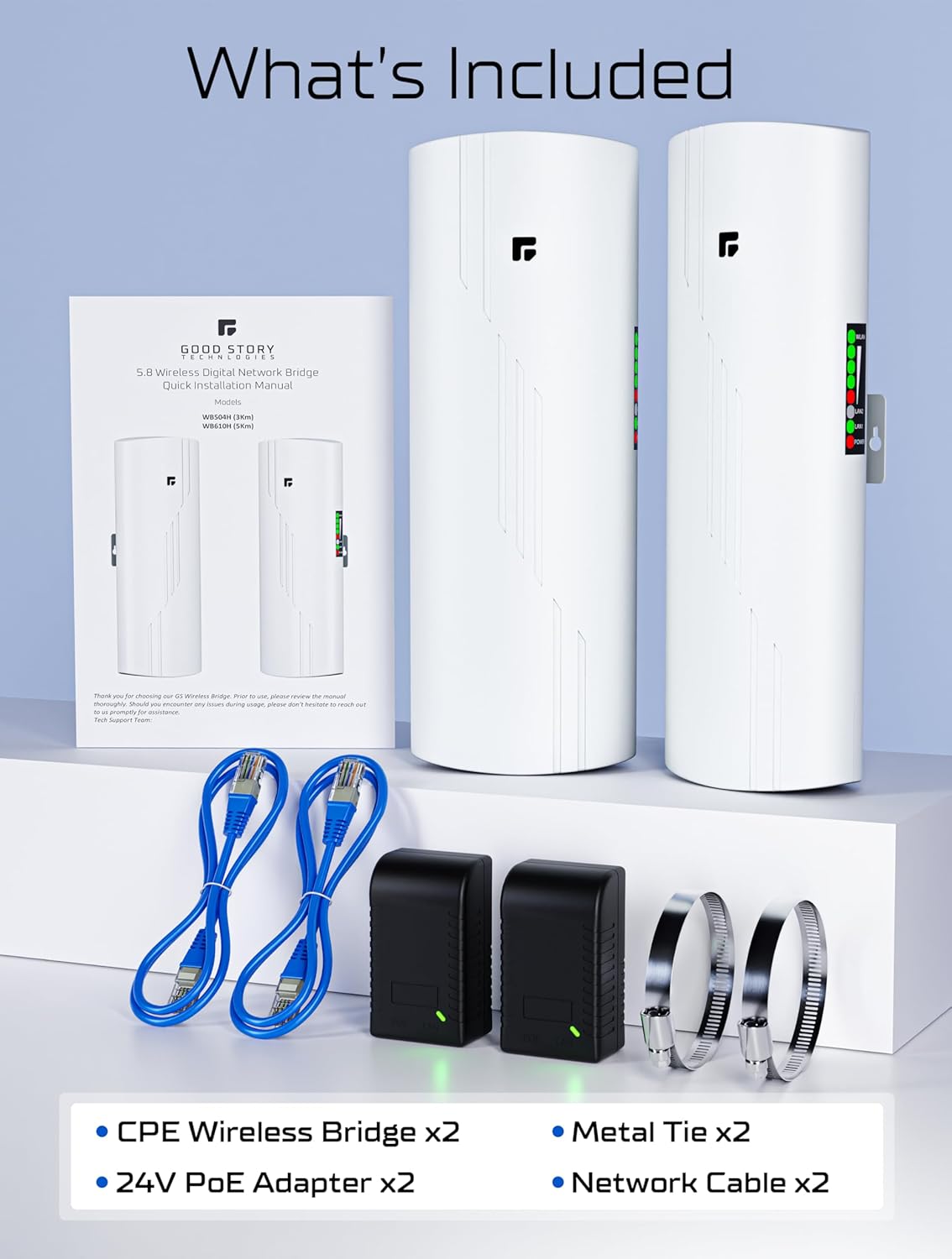
Package Contents
Please verify that all items listed below are included in your package:
- CPE Wireless Bridge Units (x2)
- 24V PoE Adapters (x2)
- Metal Ties for Mounting (x2)
- Network Cables (x2)

Product Overview
The GOOD STORY Wireless Bridge system consists of two pre-configured units designed for outdoor use. Each unit features a 16dBi high-gain antenna and operates on the 5.8GHz frequency band, supporting IEEE802.11AC protocol for wireless access speeds up to 450Mbps. The units are weather-resistant (IP65 rated) and built with Qualcomm's enterprise-class master chip for reliable performance.

Key Features:
- Long-Range High-Speed Connectivity: Extends network up to 3KM with 5.8GHz wireless.
- Pre-Configured: Units are pre-paired for plug-and-play setup.
- Weather-Resistant Design: IP65 rated for outdoor use in various climates.
- Signal Indicators: LED lights display connection status and signal strength.
Setup and Installation
The GOOD STORY Wireless Bridge system is pre-configured for ease of use. Follow these steps for a quick setup:
- Identify Units: One unit is designated as the 'Master' (Access Point) and the other as the 'Slave' (Remote Station). These are typically labeled or indicated by a switch setting.
- Connect Master Unit: Connect the Master unit to your main network router using one of the provided Ethernet cables. Plug the Ethernet cable into the POE/LAN port of the Master unit and the LAN port of the PoE adapter. Then, connect the 'LAN' port of the PoE adapter to an available LAN port on your main router. Plug the PoE adapter into a power outlet.
- Connect Slave Unit: At the secondary location, connect the Slave unit to a device (e.g., a computer, a secondary WiFi router, or a network switch) using the second Ethernet cable. Plug the Ethernet cable into the POE/LAN port of the Slave unit and the LAN port of its PoE adapter. Connect the 'LAN' port of the PoE adapter to your desired network device. Plug the PoE adapter into a power outlet.
- Mount Units: Securely mount both Master and Slave units in their respective outdoor locations. Use the provided metal ties for pole mounting or other suitable hardware for wall mounting. Ensure the units are mounted in a way that allows for a clear line of sight between them.
- Aim Units: Carefully aim the Master and Slave units directly at each other. A clear line of sight is crucial for optimal performance. The LED indicators on the units will help you gauge signal strength. More lit LEDs indicate a stronger connection.
- Verify Connection: Once powered on and aimed, the units should automatically establish a connection. Check the LED indicators on both units to confirm a stable link.

Operating the Wireless Bridge
Once properly installed and connected, the wireless bridge operates automatically. It creates a transparent network link, effectively acting as a long Ethernet cable between your main network and the remote location. The bridge units themselves do not broadcast a Wi-Fi signal for direct device connection; instead, they transmit the network signal to a connected router or device at the remote end, which then provides local Wi-Fi or wired access.
The LED indicators on the side of each unit provide visual feedback on the connection status and signal strength. A higher number of illuminated LEDs indicates a stronger and more stable wireless link between the Master and Slave units.
Applications
The GOOD STORY Wireless Bridge is versatile and can be used in various scenarios to extend network connectivity:
- Point-to-Point (P2P) Network Extension: Connect a main building to a detached guest house, barn, garage, or other outbuilding to provide internet access.
- Point-to-MultiPoint (P2MP) Network Extension: A single Master unit can connect to multiple Slave units (up to 8) to extend the network to several remote locations simultaneously.
- Security Camera Systems: Establish a reliable wireless link for IP cameras or Network Video Recorders (NVRs) in remote areas, such as surveillance for farms, parking lots, or large properties.
- Starlink Network Extension: Extend your Starlink internet connection to a remote building by connecting the Starlink modem to the Master unit and providing internet to a secondary router via the Slave unit.


Maintenance
To ensure the longevity and optimal performance of your GOOD STORY Wireless Bridge system, consider the following maintenance tips:
- Regular Inspection: Periodically check the physical condition of the units, mounting hardware, and cables for any signs of wear, damage, or corrosion.
- Clear Line of Sight: Ensure that no new obstructions (e.g., growing trees, new structures) have appeared in the line of sight between the units, which could degrade signal quality.
- Cleanliness: Gently clean the exterior of the units to remove dirt, dust, or debris that may accumulate, especially on the antenna surfaces. Use a soft, damp cloth. Do not use harsh chemicals or abrasive materials.
- Secure Connections: Verify that all Ethernet and power connections remain secure and free from moisture.
Troubleshooting
The GOOD STORY Wireless Bridge is designed for simple, plug-and-play operation. If you encounter issues, consider these common troubleshooting steps:
- No Power: Ensure both PoE adapters are securely plugged into working power outlets and that the Ethernet cables are correctly connected to the bridge units and adapters. Check for any indicator lights on the PoE adapters.
- No Link/Weak Signal:
- Verify a clear, unobstructed line of sight between the Master and Slave units.
- Re-aim the units to ensure they are pointing directly at each other. Observe the LED signal strength indicators for improvement.
- Check that Ethernet cables are properly seated in all ports.
- Ensure the Master/Slave switch (if present and adjustable) is correctly set for each unit.
- No Internet at Remote Location:
- Confirm that the main router has an active internet connection.
- Verify that the Slave unit is properly connected to a secondary router or device that is configured to provide internet access.
- Check the network settings of any devices connected to the secondary router/device.
- Slow Speed:
- Ensure optimal line of sight and maximum signal strength (all LEDs lit).
- Minimize potential sources of interference (e.g., other 5GHz devices, large metal objects).
- Test the internet speed directly from your main router to rule out issues with the primary internet connection.
Specifications
| Brand | GOOD STORY |
| Model Number | WB610H |
| Hardware Interface | Ethernet |
| Data Link Protocol | Ethernet |
| Wireless Standard | IEEE802.11AC |
| Frequency Band | 5.8GHz |
| Data Transfer Rate | Up to 450Mbps |
| Antenna Gain | 16dBi |
| Max Transmission Distance | 3KM (9800FT) |
| Weather Resistance | IP65 (Waterproof, Dust-proof, UV & Sun Resistant) |
| Compatible Devices | Desktop, Laptop, Printer, Smart TV, Tablet |
| Item Weight | 2 pounds |
| Package Dimensions | 14.37 x 7.68 x 2.91 inches |
| UPC | 196852105380 |
Warranty and Support
For warranty information, technical support, or any questions regarding your GOOD STORY Wireless Bridge system, please refer to the contact information provided with your product packaging or visit the official GOOD STORY website. Our support team is available to assist you with any issues or inquiries.