1. Introduction
This manual provides detailed instructions for the Teyleten Robot TP4056 Type-C Li-ion Battery Charger and DC-DC Step Up Boost Module. This versatile module is designed for charging single 3.7V Li-ion batteries to 4.2V and providing an adjustable boosted output voltage. It is suitable for various DIY electronic projects requiring battery charging and voltage boosting capabilities.

Figure 1: Top view of the Teyleten Robot TP4056 module, showing the Type-C port, inductor, and potentiometer.
2. Specifications
- Input Voltage Range: 4.2V to 6.5V (Recommended 5V)
- Charging Current: Max 1A (Programmable)
- Battery Type: Single 3.7V Li-ion (charges to 4.2V)
- Output Voltage: 4.2V to 28V (Adjustable)
- Maximum Output Power: 5W
- Charging Method: Constant Current/Constant Voltage (CC/CV)
- Protections: Over-temperature protection, Battery reverse connection protection, 0V activation, 2.9V trickle charge
- Standby Current: Low power standby
- Operating Temperature: -40℃ to 80℃
- Input Interface: USB Type-C port and solder pads (IN+, IN-)
- Output Interface: Solder pads (VO+, VO-)
- Battery Interface: Solder pads (B+, B-)
3. Setup and Connections
Proper connection of the module is crucial for safe and effective operation. Refer to the diagrams below for connection points.
3.1 Input Power Connection
The module supports two methods for input power:
- USB Type-C Port: Connect a standard 5V USB Type-C power adapter to the Type-C port on the module.
- Solder Pads: Alternatively, solder your 4.2V-6.5V (recommended 5V) power source to the IN+ and IN- pads located on the back of the module. Choose only one input method.

Figure 2: Bottom view of the module, indicating IN+, IN-, VO+, VO-, B+, and B- solder pads.
3.2 Battery Connection
Connect your 3.7V Li-ion battery to the B+ and B- solder pads. Ensure correct polarity to prevent damage to the battery and module. The module includes battery reverse connection protection.
3.3 Output Connection
The module provides two sets of output solder pads, VO+ and VO-, which are connected in parallel. You can use either set to connect your load. The output voltage can be adjusted as described in Section 5.2.
4. Operation
4.1 Charging Process
Once the input power and battery are connected, the module will begin charging the Li-ion battery. The charging process follows a Constant Current/Constant Voltage (CC/CV) method, ensuring efficient and safe charging up to 4.2V.
4.2 LED Indicators
The module features two LEDs to indicate its status:
- CHRG (Red LED): This LED illuminates when the battery is actively charging.
- STDBY (Blue LED): This LED illuminates when charging is complete.
Status Interpretation:
- Charging: Red LED is bright, Blue LED is off.
- Charging Complete: Blue LED is bright, Red LED is slightly bright or off.
- No Battery/No Load (Boost Output Active): Blue LED is on, Red LED is slightly bright.
5. Adjustments
5.1 Charging Current Adjustment
The charging current can be adjusted by changing the value of a specific resistor on the module. This resistor is typically a 0603 package. Modifying this component carries risks and should only be performed by experienced users. The manufacturer is not responsible for issues arising from such modifications.
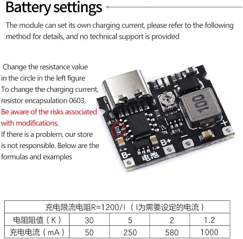
Figure 3: Location of the resistor for charging current adjustment.
The formula for calculating the charging current limiting resistor (R) is approximately: R = 1200 / I (where I is the desired current in Amperes).
Examples:
| Resistance Value (KΩ) | Charging Current (mA) |
|---|---|
| 30 | 50 |
| 5 | 250 |
| 2 | 580 |
| 1.2 | 1000 (1A) |
5.2 Output Voltage Adjustment
The output voltage (VO+, VO-) can be adjusted using the onboard potentiometer. Use a small screwdriver to carefully turn the potentiometer to set the desired output voltage between 4.2V and 28V.
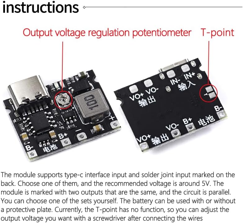
Figure 4: Location of the output voltage regulation potentiometer.
6. Safety Precautions
- Always ensure correct polarity when connecting the battery and power input.
- Do not exceed the maximum input voltage of 6.5V.
- Do not exceed the maximum output power of 5W.
- Handle Li-ion batteries with care. Avoid short circuits, overcharging, or physical damage.
- Modifications to the charging current resistor should be done with caution and understanding of electronics.
- Keep the module away from moisture and extreme temperatures.
- This module is intended for DIY use by individuals with sufficient electronic knowledge.
7. Troubleshooting
- Module not powering on: Check input power connection and voltage. Ensure Type-C cable is functional or solder pads are correctly connected.
- Battery not charging: Verify battery connection polarity (B+, B-). Check if the battery is deeply discharged (below 2.9V, module has trickle charge feature). Ensure input power is stable.
- No output voltage: Check if the potentiometer has been adjusted correctly. Ensure a load is connected to the output.
- Incorrect charging current: If you have modified the current-setting resistor, double-check its value and soldering.
- Overheating: Ensure the module is not overloaded (exceeding 5W output) and has adequate ventilation.
8. Maintenance
The Teyleten Robot TP4056 module requires minimal maintenance. Keep the module clean and free from dust and debris. Avoid exposing it to liquids or corrosive environments. Periodically inspect solder joints for integrity if the module is subject to vibration or frequent handling.
9. Warranty and Support
For specific warranty information or technical support, please refer to the retailer or manufacturer's official website where the product was purchased. General support for DIY components typically involves ensuring proper handling and usage according to specifications.


