Ifme PN2098
PN2098 Pressure Sensor User Manual
Model: PN2098
Product Overview
The Ifme PN2098 is a high-precision pressure sensor designed for fluid applications. It features an integrated display for direct reading of pressure values, and offers versatile output options including two PNP/NPN switch outputs and one analog current/voltage output. This sensor is suitable for industrial environments requiring accurate pressure monitoring within a range of -12.5 to 250 mbar.
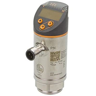
Image: Front view of the Ifme PN2098 Pressure Sensor, showing the digital display, control buttons, M12 electrical connector, and G1/4 process connection.
Specifications
| Model | PN2098 |
| Measurement Range | -12.5 to 250 mbar |
| Supply Voltage | 18-30VDC |
| Outputs | 2 x PNP/NPN switch outputs, 1 x Analog (Current/Voltage) output |
| Process Connection | G1/4 Internal |
| Electrical Connection | M12 Connector |
| Display | Integrated Digital Display |
| Manufacturer | IFM EFECTOR |
Setup and Installation
Proper installation is crucial for the accurate and safe operation of the PN2098 pressure sensor. Ensure all connections are secure and meet local electrical and safety codes.
- Mounting: Securely mount the sensor using the G1/4 internal thread into the process connection point. Ensure the mounting location is free from excessive vibration and extreme temperatures outside the sensor's operating range.
- Electrical Connection: Connect the M12 connector to a compatible power supply (18-30VDC) and control system. Refer to the wiring diagram provided with the sensor for correct pin assignments for power, switch outputs, and analog output.
- Power On: Apply power to the sensor. The integrated display should illuminate and show the current pressure reading.
- Initial Configuration: If necessary, use the buttons on the sensor's display to access the menu for initial parameter settings, such as pressure units, switching points for the digital outputs, or analog output scaling. Consult the detailed programming guide for specific menu navigation.
Operating Instructions
Once installed and configured, the PN2098 sensor operates continuously to monitor fluid pressure. The display provides real-time pressure values.
- Reading the Display: The integrated digital display shows the current pressure value. The units can typically be configured (e.g., mbar, psi, kPa).
- Monitoring Outputs: The two switch outputs will activate or deactivate based on the configured pressure thresholds. The analog output will provide a proportional signal (current or voltage) corresponding to the measured pressure, which can be read by a PLC or control system.
- Parameter Adjustment: For advanced settings or recalibration, refer to the sensor's programming manual. Access to the configuration menu is typically secured to prevent accidental changes.
Maintenance
The PN2098 pressure sensor is designed for robust industrial use and requires minimal maintenance. Regular checks can help ensure long-term reliability.
- Cleaning: Periodically clean the sensor's exterior, especially the display, with a soft, damp cloth. Do not use abrasive cleaners or solvents.
- Connection Check: Verify that the electrical and process connections remain secure and free from corrosion or damage.
- Calibration Check: Depending on the application and industry standards, periodic calibration checks may be required to ensure continued accuracy. Refer to your facility's calibration procedures.
- Environmental Conditions: Ensure the sensor operates within its specified environmental limits (temperature, humidity) to prevent damage.
Troubleshooting
This section provides guidance for common issues encountered during the operation of the PN2098 pressure sensor.
| Problem | Possible Cause | Solution |
|---|---|---|
| No display or power | No power supply; incorrect wiring; faulty cable. | Check power supply voltage (18-30VDC). Verify wiring according to the diagram. Inspect M12 cable for damage. |
| Incorrect pressure reading | Sensor not properly installed; air in process line; sensor out of calibration; incorrect unit setting. | Ensure proper sealing of process connection. Bleed air from the system. Perform a calibration check. Verify display unit settings. |
| Switch output not activating | Incorrect switching point setting; wiring issue; pressure not reaching threshold. | Check and adjust switching point parameters in the sensor menu. Verify output wiring. Confirm pressure is within the set range. |
| Analog output incorrect | Incorrect scaling; wiring issue; load impedance mismatch. | Verify analog output scaling in the sensor menu. Check wiring to the PLC/controller. Ensure the receiving device's input impedance is compatible. |
If the problem persists after attempting these solutions, please contact technical support.
Warranty and Support
For information regarding product warranty, technical support, or service, please contact the manufacturer, Ifme, or your authorized distributor. Keep your purchase receipt and product serial number (if applicable) readily available when seeking support.
Manufacturer: IFM EFECTOR
Please refer to the official IFM EFECTOR website or product documentation for the most current contact information and warranty terms.