1. Introduction
Thank you for choosing the GOLDEN BLUE SZ01 Smart Digital Multimeter. This device is a battery-driven, auto-ranging digital multimeter with True RMS capabilities, designed for accurate measurement of various electrical parameters. It features a 6000-count LCD display with backlight for clear readings, and includes functions such as voltage, current, resistance, continuity, diode, frequency, non-contact voltage detection (NCV), and live wire measurement.
This manual provides detailed instructions for the safe and effective operation, maintenance, and troubleshooting of your SZ01 multimeter. Please read it thoroughly before use and keep it for future reference.
2. Safety Information
WARNING: To avoid possible electric shock, fire, or personal injury, please read all safety information before you use the product.
- Always ensure the multimeter is in the correct function mode and range before making measurements.
- Do not exceed the maximum input values for any function.
- Do not use the meter if it or the test leads appear damaged.
- Exercise extreme caution when working with voltages above 30V AC RMS, 42V peak, or 60V DC. Such voltages pose a shock hazard.
- Always disconnect the test leads from the circuit before changing functions.
- Replace the batteries as soon as the low battery indicator appears to ensure accurate readings.
- Do not operate the meter in explosive gas, vapor, or dust environments.
3. Product Overview
3.1. Components
The SZ01 Smart Digital Multimeter comes with the main unit and a pair of test leads (red and black).

Figure 3.1: The SZ01 Smart Digital Multimeter, showing the main unit, test leads, and product packaging.
3.2. Dimensions
The compact design of the SZ01 multimeter makes it easy to handle and store.

Figure 3.2: Physical dimensions of the SZ01 multimeter, approximately 127mm (5 inches) in length, 67mm (2.64 inches) in width, and 29.2mm (1.15 inches) in thickness.
3.3. Display and Controls
The multimeter features a large LCD display with a backlight for clear visibility in various lighting conditions. The display shows measurement readings, units, and function indicators. Controls include function buttons and input jacks for test leads.

Figure 3.3: The backlit digital display of the SZ01 multimeter, showing various measurement parameters and the "Hold" function. Press and hold the backlight key to activate the backlight.
4. Setup
4.1. Battery Installation
The SZ01 multimeter requires 2 x AAA batteries (not included) for operation.
- Locate the battery compartment cover on the back of the multimeter.
- Use a screwdriver to open the battery compartment.
- Insert 2 AAA batteries, ensuring correct polarity (+ and -).
- Replace the battery compartment cover and secure it with the screw.
A low battery indication will appear on the display when the batteries need replacement.
5. Operation
The SZ01 multimeter is an auto-ranging device, simplifying operation by automatically selecting the appropriate measurement range. Ensure test leads are properly inserted into the COM and INPUT jacks for most measurements.
5.1. DC Current Measurement
To measure DC current, connect the multimeter in series with the circuit. For currents up to 600mA, use the mA input. For currents up to 10A, use the 10A input. The red test lead should be inserted into the current input jack.

Figure 5.1: Examples of various measurement types. Top left shows DC current measurement, connected in series with a strip light. Top middle shows AC current measurement with a light bulb. Top right shows resistance measurement.
5.2. AC Current Measurement
Similar to DC current, connect the multimeter in series. Adjust to the corresponding AC current range. Ensure the red test lead is in the correct current input jack.
Refer to Figure 5.1 (top middle) for an illustration of AC current measurement.
5.3. Resistance Measurement
To measure resistance, ensure the circuit is de-energized. Touch the test leads to both ends of the resistor. The multimeter will automatically recognize and display the resistance value.
Refer to Figure 5.1 (top right) for an illustration of resistance measurement.
5.4. DC Voltage Measurement
Connect the test leads in parallel across the component or circuit to measure DC voltage. The multimeter will automatically select the appropriate range.
Refer to Figure 5.1 (bottom left) for an illustration of DC voltage measurement.
5.5. AC Voltage Measurement
Connect the test leads in parallel across the AC voltage source. The multimeter will automatically select the appropriate range.
Refer to Figure 5.1 (bottom middle) for an illustration of AC voltage measurement.
5.6. On-off Buzzer Detection (Continuity)
This function automatically recognizes and detects the test lead line on/off. If there is a buzzer sound, it indicates continuity. No sound indicates an open circuit.
Refer to Figure 5.1 (bottom right) for an illustration of on-off buzzer detection.
5.7. NCV (Non-Contact Voltage) Detection
Press and hold the NCV button after booting the device. Bring the top of the multimeter close to an AC voltage source. The strip lights on both sides of the screen will change synchronously with the intensity of the electric field, indicating the presence of voltage without direct contact.
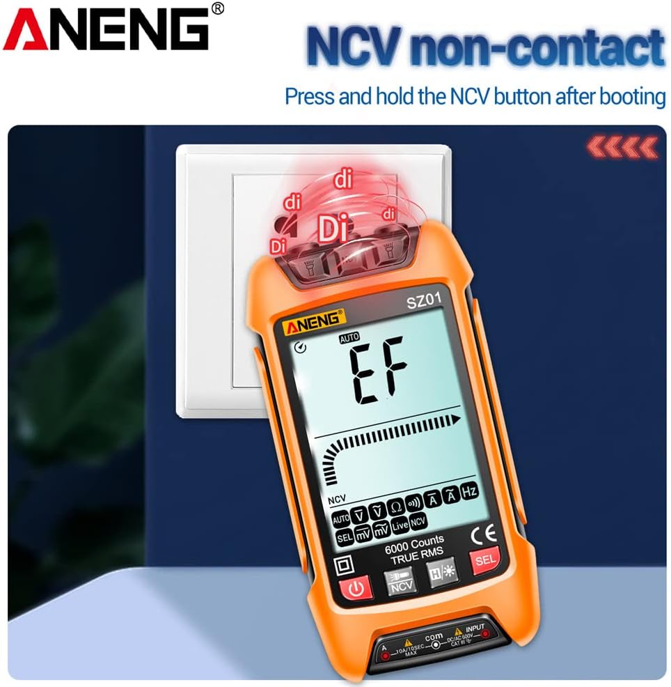
Figure 5.2: Demonstrating the NCV (Non-Contact Voltage) detection feature, showing the multimeter detecting voltage near an electrical outlet.
5.8. Zero Fire Wire Identification (Live Wire Detection)
Insert one test lead into a socket hole. The screen will indicate "Live" and a fast beeping sound will occur if it's the live wire. If it's the neutral line, the screen will show no beep and a different indication.

Figure 5.3: Illustration of Zero Fire Wire Identification. The left image shows detection of a neutral line (zero line) with no beep. The right image shows detection of a live wire (FireWire) with a fast beeping sound.
5.9. LED Flashlight
The multimeter is equipped with an LED flashlight for convenience when working in dimly lit areas. Press and hold the flashlight button to turn it on or off.

Figure 5.4: The SZ01 multimeter with its integrated LED flashlight activated, providing illumination for measurements in dark environments.
5.10. Automatic Shutdown
To conserve battery life, the multimeter will automatically shut down after 15 minutes of inactivity.
6. Specifications
Below are the detailed technical specifications for the SZ01 Smart Digital Multimeter.

Figure 6.1: Detailed specifications table for the SZ01 multimeter, including function, range, resolution, and accuracy for various measurements.
| Parameter | Value |
|---|---|
| Model | SZ01 |
| Display Type | Digital display, 6000 Counts, LCD with Backlight |
| True RMS | Yes |
| AC Current Range | 600.0mA / 10A |
| DC Current Range | 600.0mA / 10A |
| DC Voltage Range | 600.0mV / 6.000V / 60.00V / 600.0V |
| AC Voltage Range | 600.0mV / 6.000V / 60.00V / 600.0V |
| Resistance Range | 600.0Ω / 6.000kΩ / 60.00kΩ / 600.0kΩ / 6.000MΩ / 60.00MΩ |
| Frequency Range | 100Hz / 1000Hz |
| Continuity Test | Yes |
| NCV (Non-Contact Voltage) | Yes |
| Automatic Shutdown | After 15 minutes of inactivity |
| Power Supply | 2 x AAA batteries (not included) |
| Shell Material | ABS |
| Dimensions | Approx. 127x67x29.2mm (5x2.64x1.15in) |
| Color | Orange |
7. Maintenance
7.1. Cleaning
Wipe the case with a damp cloth and mild detergent. Do not use abrasives or solvents. Keep the input terminals free of dirt or debris.
7.2. Battery Replacement
When the low battery indicator appears on the display, replace the batteries promptly to ensure accurate readings and proper operation. Refer to Section 4.1 for battery installation instructions.
7.3. Test Lead Care
Inspect test leads for damaged insulation or exposed metal before each use. Replace damaged leads immediately.
8. Troubleshooting
| Problem | Possible Cause | Solution |
|---|---|---|
| Meter does not power on. | Dead or incorrectly installed batteries. | Check battery polarity; replace batteries. |
| No reading or "OL" displayed. | Open circuit; measurement range exceeded; incorrect function selected. | Check circuit continuity; ensure measurement is within range; select correct function. |
| Inaccurate readings. | Low battery; damaged test leads; environmental interference. | Replace batteries; inspect and replace test leads; move away from strong electromagnetic fields. |
| Buzzer not working for continuity. | Open circuit; function not selected. | Ensure circuit is closed; verify continuity function is active. |
9. Warranty and Support
GOLDEN BLUE products are manufactured to high-quality standards. For any issues or support inquiries, please contact your retailer or the manufacturer directly. Please retain your proof of purchase for warranty claims.