1. Introduction
This manual provides essential instructions for the installation, operation, and maintenance of your CNEEL EEL Programmable Smart BMS 16S 48V 100A. This Battery Management System is designed to protect and optimize the performance of 16S 48V LiFePO4 battery packs, supporting various communication protocols and parallel operations.
2. Product Features
- Parallel Operation: Supports up to 16 units in parallel, enhancing battery system scalability and efficiency up to 95%.
- Comprehensive Protection: Includes passive balance, individual cell over-voltage protection, over/under-voltage protection, temperature protection, overcharge/discharge protection, over current protection, and short circuit protection.
- Advanced Communication: Equipped with CANBUS and RS485 communication interfaces for seamless integration with inverters and PC monitoring.
- Proprietary Software: Features multi-language PC software for detailed BMS and battery system settings, allowing real-time status monitoring.
- Wide Inverter Compatibility: Compatible with approximately 80% of inverters on the market, including Pylontech, Goodwe, and Growatt.
3. Package Contents
Please verify that all items are present in your package:
- EEL Smart BMS (with CAN/RS485 and temperature sensor) x 1
- Connection cable x 1
- PC connection wire x 1
- LCD screen x 1 (Optional, included if specified in your order)
4. Setup and Installation
Careful installation is crucial for the safe and efficient operation of the BMS. Ensure all connections are secure and correctly polarized.
4.1 BMS Board Overview

Image: The EEL Smart BMS board, highlighting the CANBUS and RS485 communication ports and DIP switches for address configuration.
The BMS board features dedicated ports for CANBUS and RS485 communication. The CANBUS interface is used for communication between the battery and inverters, typically at a baud rate of 500kbps. The RS485 interface facilitates communication between parallel battery packs or between the BMS and a PC, with a baud rate of 19200bps.
4.2 Connecting the LCD Screen (Optional)

Image: The EEL Smart BMS board shown with the optional LCD screen connected via a ribbon cable and multi-colored wires.
If your package includes an LCD screen, connect it to the designated port on the BMS board using the provided ribbon cable and connection wires. The LCD screen allows for direct monitoring and basic configuration without a computer.
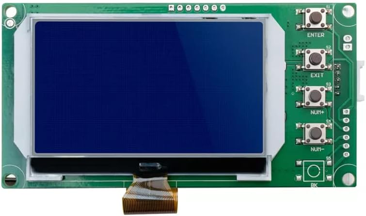
Image: A detailed view of the optional LCD screen, showing its display area and control buttons (ENTER, EXIT, NUM+, NUM-).
4.3 Wiring Connections
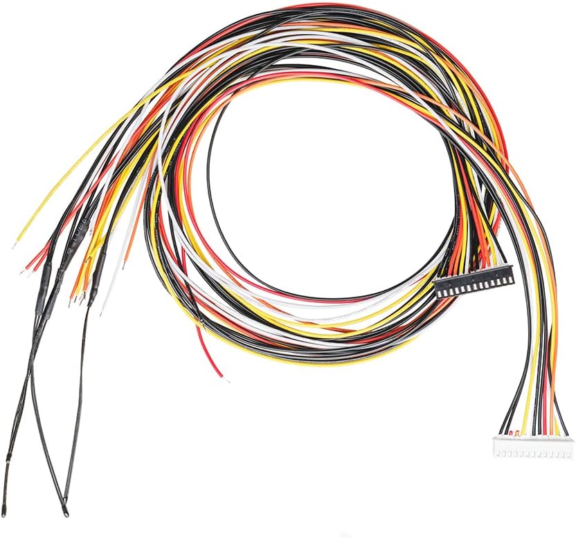
Image: A bundle of multi-colored wires with a connector, used for connecting individual battery cells to the BMS for balancing and monitoring.
Connect the provided balance wires to your battery cells according to the wiring diagram specific to your 16S LiFePO4 battery pack. Ensure correct voltage sensing for each cell. Connect the main battery positive and negative terminals to the corresponding terminals on the BMS.
5. Operating Instructions
Once installed, the BMS continuously monitors and protects your battery pack. For advanced monitoring and configuration, use the dedicated PC software.
5.1 Parallel Operation
The EEL Smart BMS supports connecting up to 16 units in parallel. This allows for increased capacity and power output. Ensure proper communication wiring between parallel BMS units using the RS485 interface and configure the unique address for each BMS using the DIP switches on the board.
5.2 Passive Balancing
The BMS features passive balancing to equalize the voltage across individual battery cells, extending the overall lifespan and performance of the battery pack. This process occurs automatically when cell voltage differences are detected.
6. Software Configuration and Monitoring
The EEL BMS comes with proprietary multi-language PC software for detailed configuration and real-time monitoring of your battery system.
6.1 PC Connection

Image: A diagram illustrating the connection of the BMS to a laptop via an RS485 interface and a USB to RS485 adapter cable for software communication.
To connect the BMS to your computer, use the provided PC connection wire (USB to RS485 adapter cable). Plug the RS485 end into one of the RS485 ports on the BMS and the USB end into your computer. Install the necessary drivers and the EEL BMS software on your PC.
6.2 Software Features
- Real-time Status: View battery voltage, current, cell voltages, temperature, and protection status.
- Parameter Settings: Adjust various protection thresholds, balancing parameters, and communication settings.
- Data Logging: Record and analyze historical battery data.
Important: The communication line interface definition and upper computer baud rate are critical. For CAN communication, the baud rate is 19200bps. For other communications, it is typically 9600bps. Refer to the software documentation for specific settings.
7. Inverter Compatibility
The EEL Smart BMS is designed for broad compatibility with various inverters.

Image: A graphic displaying logos of several inverter brands, including Growatt, SMA, Goodwe, Victron Energy, and others, indicating wide compatibility with the EEL Smart BMS.
The BMS supports approximately 80% of inverters currently available, including popular brands like Pylontech, Goodwe, and Growatt. Compatibility can often be automatically matched or manually switched via the software.
If your inverter brand is not listed or does not automatically connect, please contact your inverter supplier to obtain their communication protocol. You can then provide this protocol to CNEEL support for assistance in defining and integrating it with the BMS.
8. Maintenance
The EEL Smart BMS is designed for reliable operation with minimal maintenance. However, periodic checks are recommended:
- Visual Inspection: Regularly inspect the BMS and all connections for any signs of damage, corrosion, or loose wiring.
- Software Monitoring: Use the PC software to monitor battery health, cell balance, and temperature trends. Address any anomalies promptly.
- Firmware Updates: Check the manufacturer's website for any available firmware updates for the BMS to ensure optimal performance and access to new features.
9. Troubleshooting
If you encounter issues with your EEL Smart BMS, consider the following common troubleshooting steps:
- No Power/No Display: Check all power connections to the BMS and the battery pack. Ensure the battery voltage is within the operational range.
- Communication Issues: Verify that communication cables (CANBUS, RS485) are correctly connected and not damaged. Confirm the baud rate settings in the software match the BMS configuration. Check DIP switch settings for unique addresses in parallel systems.
- Protection Triggered: If the BMS triggers a protection (e.g., over-voltage, under-voltage, over-current), identify the cause. This could be due to an imbalanced cell, excessive load, or charging issues. Address the root cause before resetting the BMS.
- Cell Imbalance: Allow the BMS to perform passive balancing. If severe or persistent, check individual cell connections and health.
For persistent issues or complex problems, please contact CNEEL technical support.
10. Specifications
| Feature | Specification |
|---|---|
| Model Number | 16S 48V 100A |
| Brand | CNEEL |
| Output Voltage | 48 Volts (DC) |
| Power Source | Battery Powered |
| Date First Available | October 10, 2022 |
| Manufacturer | EEL BATTERY |
11. Warranty and Support
For warranty information, please refer to the documentation provided with your purchase or contact CNEEL customer service directly. If you require technical assistance or have questions regarding the operation or installation of your EEL Smart BMS, please reach out to CNEEL support through their official channels. You can find more information and contact details on the CNEEL Brand Store.