1. Product Overview
The Abestop ET618+7 ID Mapping device is a versatile 2-in-1 tool designed for network professionals and electricians. It integrates the functionalities of an Ethernet cable tester, an electrical wire tracer, and a multifunctional digital multimeter into a single, compact unit. This device is ideal for communication wiring, engineering maintenance, radio tracking, manufacturing, and laboratory applications.

Image: The ET618+7 ID Mapping main unit, wire tracker receiver, and various accessories including test leads, alligator clips, USB cable, and ID mapping remotes.

Image: A visual representation highlighting the device's capabilities as an Ethernet Cable Tester, Circuit Tracer, and Multimeter.
Key Features:
- Integrated Functionality: Combines Ethernet cable testing, electrical wire tracing, and a full multimeter.
- Advanced Wire Tracing: Features a professional analog tone generator with adjustable sensitivity and a silent vibration mode. Tracing distance up to 3km.
- Cable Length Measurement: Accurate measurement for network, telephone, and video coax cables up to 500 meters with manual calibration option.
- Network Cable Testing: Visualized RJ45 wiring diagram on display and 8 indicators on the receiver for quick status checks and remote ID mapping.
- Multimeter Capabilities: Measures temperature, continuity, voltage (AC/DC), current (AC/DC), resistance, diode, and NCV (Non-Contact Voltage).
- Rechargeable Battery: Main unit equipped with a 1250 mAh lithium battery, offering 8 hours of continuous working time after 3 hours of charging.

Image: Detailed diagram labeling the components of the main unit (Display Screen, NCV Detection sensing Area, Main, Length, Charging Port, LED lighting) and the wire tracker receiver (Tracing Sensor, Flashlight, Sound/Sensitivity adjusting wheel, Flashlight Switch, Mode Button, Indicators, RJ45 Cable Jack, DMM Input Jack).
2. Setup and Battery Information
2.1 Unpacking and Initial Inspection
Carefully unpack all components and verify against the packing list. Ensure no damage occurred during transit. The package should include the main unit, wire tracker receiver, 7 ID mapping remotes, alligator clip & RJ45 cable, K-type temperature probe, multimeter leads, USB cable, and a 9V battery.

Image: A visual display of all accessories provided with the ET618+7 ID Mapping kit, including cables, probes, and ID adapters.
2.2 Battery Installation and Charging
- Main Unit: The main unit is equipped with a replaceable 1250 mAh lithium battery. To charge, connect the provided USB cable to the charging port on the main unit and a 5V/2A charger (not included). A full charge takes approximately 3 hours and provides up to 8 hours of continuous operation or several months of standby time.
- Receiver Unit: The receiver unit uses a 9V battery (included). Open the battery compartment on the back of the receiver, insert the 9V battery, and close the compartment. The receiver offers up to 2 hours of continuous working time.

Image: Visual representation of the main unit's rechargeable 1250mAh lithium battery, showing 8 hours working time and 3 hours charging time, alongside the receiver's 9V battery.
3. Operating Instructions
The ET618+7 ID Mapping device features intuitive controls. Use the MODE button to switch to circuit tracer functions and the DMM button for multimeter functions.

Image: A collage demonstrating key functions: Cable Length Measurement (up to 500m), Cable Status Indicator, Quick Checking on Switch (port flashing), and Remote ID Mapping.
3.1 Network Cable Testing
This function allows for comprehensive testing of network cables, including length measurement, wiring diagram verification, and remote ID mapping.
- Cable Length Measurement: Connect one end of the cable to the main unit's RJ45 port and the other end to the remote unit (or leave open for open-circuit testing). Select the LENGTH mode. The device can measure cable lengths up to 500 meters. Manual calibration is available for enhanced accuracy.
- Wiring Diagram Verification: Connect the RJ45 cable to the main unit. The display will visualize the Ethernet wiring diagram, indicating correct connections or faults. The 8 indicators on the wire tracker receiver also show the status.
- Quick Checking on Switch: Connect the main unit to a network switch port. The indicator of the connected port on the switch will flash, allowing for quick identification of active ports.
- Remote ID Mapping: Use the included 7 ID mapping remotes to identify multiple network cables simultaneously. Connect each remote to a different cable end, and the main unit will display the corresponding ID for each cable.

Image: The wire tracker receiver indicating active (green) and defective (red) Ethernet cable connections.

Image: The main unit displaying a cable length measurement of 500.0 meters, demonstrating its capability for long cable runs.

Image: The main unit connected to a network switch, illustrating the quick positioning mode where the connected port's indicator flashes.


Image: The set of 7 remote ID mappers used for identifying multiple network cables simultaneously.
3.2 Wire Tracing
The wire tracing function helps locate and identify cables within walls, conduits, or bundles.
- Using the Tone Generator: Connect the main unit to the cable you wish to trace. Switch the main unit to MODE for circuit tracer.
- Tracing with Receiver: Use the wire tracker receiver to follow the tone emitted by the main unit. The receiver rings louder as it gets closer to the target cable.
- Adjustable Sensitivity: Adjust the sensitivity wheel on the receiver to narrow down the tracing range and pinpoint the exact location.
- Silent Vibration Mode: For discreet tracing, activate the silent vibration mode on the receiver.
- Search Modes: The device supports Digital Search Mode for both live and dead wires (less noise) and Analogue Search Mode for only dead wires (power saving). Press the SCAN button to switch between these modes.

Image: The wire tracker receiver being used to trace a cable, highlighting its adjustable sound and sensitivity, and silent vibration mode.

Image: The main unit and receiver demonstrating wire tracing over a distance of up to 3km, with icons for Digital Search Mode, Analogue Search Mode, and the SCAN button.
3.3 Multifunctional Multimeter
The integrated multimeter provides various electrical measurement capabilities. Press the DMM button to access multimeter functions.
- Continuity Test: Checks for electrical continuity in circuits. Beeps if resistance is less than 50Ω.
- Temperature Measurement: Use the K-type temperature probe to measure temperature from -20 to 1000°C.
- NCV (Non-Contact Voltage) Detection: Detects AC voltage without direct contact, enhancing safety.
- Voltage Measurement: Measures DC Voltage (400mV to 1000V) and AC Voltage (4V to 400V).
- Current Measurement: Measures DC Current (1.0 to 10.0A) and AC Current (1.0 to 10.0A).
- Resistance Measurement: Measures resistance from 200Ω to 20MΩ.
- Diode Test: Tests the functionality of diodes.
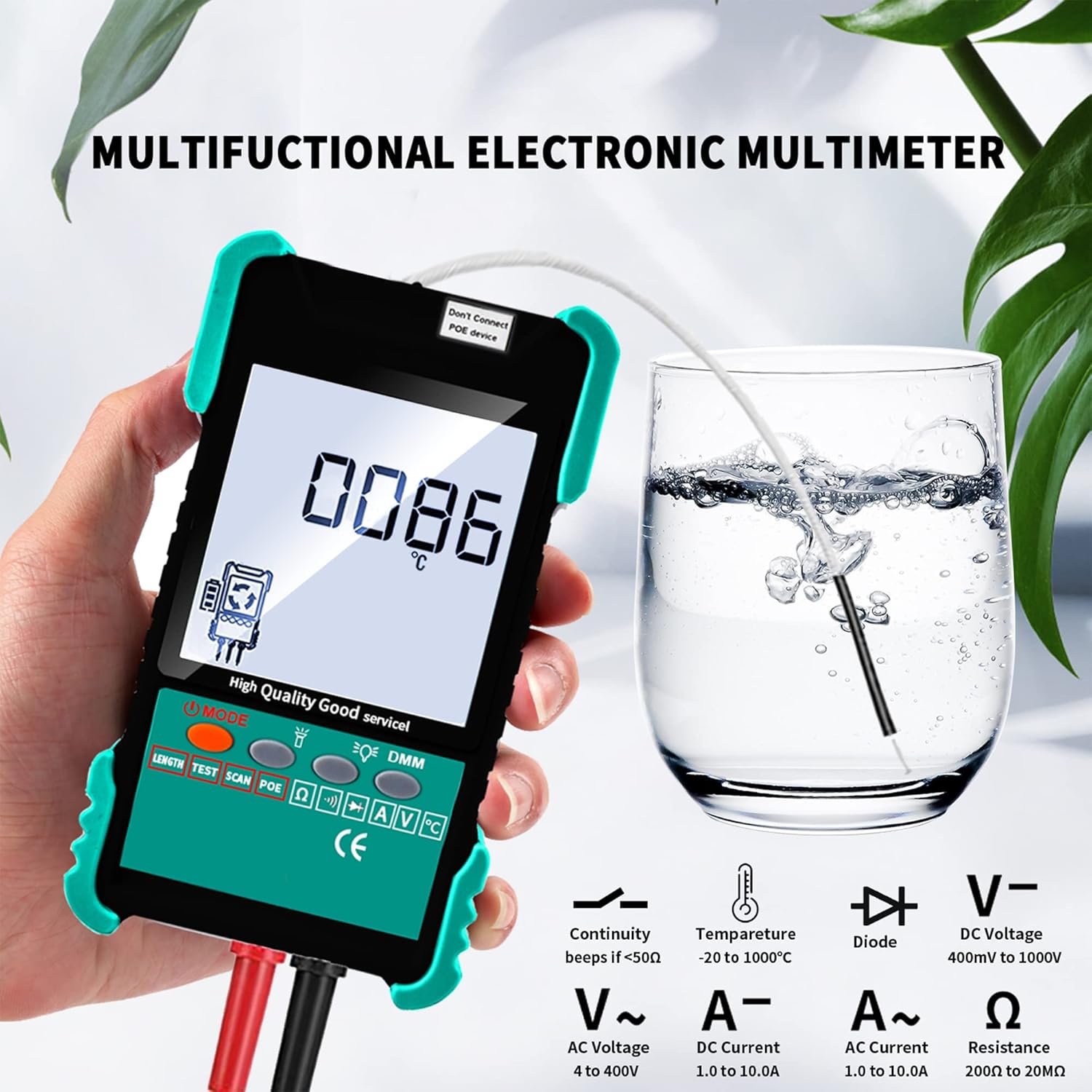
Image: The main unit displaying a temperature reading, with icons indicating its capabilities for Continuity, Temperature, Diode, DC Voltage, AC Voltage, DC Current, AC Current, and Resistance measurements.

Image: A comprehensive display of the multimeter's functions, including Continuity, Temperature, NCV, Current, DC Voltage, AC Voltage, Resistance, and Diode tests.
3.4 Connectable Cables
The ET618+7 ID Mapping device is compatible with a variety of cable types for testing and tracing.

Image: Visual representation of cable types compatible with the device, including Ethernet Plug, Telephone Wire, RVV Cable, Cat5/Cat6 Cables, and Video Coax Cables.
4. Maintenance
Proper maintenance ensures the longevity and accuracy of your ET618+7 ID Mapping device.
- Cleaning: Use a soft, dry cloth to clean the device. Do not use abrasive cleaners or solvents.
- Battery Care: Recharge the main unit's lithium battery regularly, even if not in frequent use, to maintain battery health. Remove the 9V battery from the receiver if storing the device for extended periods to prevent leakage.
- Storage: Store the device and its accessories in a cool, dry place, away from direct sunlight and extreme temperatures. Keep it in its original packaging or a protective case to prevent damage.
- Calibration: While the device offers manual calibration for length measurement, periodic professional calibration may be required for highly precise applications.
5. Troubleshooting
If you encounter issues with your ET618+7 ID Mapping device, refer to the following common troubleshooting steps:
| Problem | Possible Cause | Solution |
|---|---|---|
| Device does not power on. | Low battery or dead battery. | Charge the main unit. Replace the 9V battery in the receiver. |
| Inaccurate cable length measurement. | Cable type not properly selected or manual calibration needed. | Ensure correct cable type is selected. Perform manual calibration as per instructions. |
| Wire tracing signal is weak or noisy. | Receiver sensitivity too low; interference from other cables/devices. | Adjust the sensitivity wheel on the receiver. Try Digital Search Mode for less noise. Ensure proper grounding. |
| Multimeter readings are inconsistent. | Poor connection of test leads; low battery. | Ensure test leads are securely connected. Check battery level and recharge/replace if necessary. |
| Remote ID mapping not working. | Remote ID unit not properly connected or damaged. | Ensure remote ID unit is firmly connected to the cable. Try a different remote ID unit if available. |
If the problem persists after attempting these solutions, please contact Abestop customer support for further assistance.
6. Specifications
| Feature | Specification |
|---|---|
| Model Number | 7ID_ET618 |
| Product Dimensions | 4.3 x 1.2 x 7.5 inches (Main Unit) |
| Item Weight | 1.63 Pounds |
| Power Source (Main Unit) | Rechargeable 1250 mAh Lithium Battery |
| Power Source (Receiver) | 1 x 9V Battery (included) |
| Main Unit Charging Time | Approx. 3 hours (with 5V/2A charger) |
| Main Unit Working Time | Approx. 8 hours (continuous) |
| Receiver Working Time | Approx. 2 hours (continuous) |
| Cable Length Measurement Range | Up to 500 meters |
| Wire Tracing Distance | Up to 3 kilometers |
| Multimeter Functions | Continuity, Temperature, NCV, Voltage (AC/DC), Current (AC/DC), Resistance, Diode |
| Color | Green |
| Manufacturer | Abestop |
| Date First Available | October 10, 2022 |
7. Warranty and Support
7.1 Warranty Information
For specific warranty terms and conditions, please refer to the documentation included with your purchase or contact Abestop directly. Warranty coverage typically includes defects in materials and workmanship under normal use.
7.2 Customer Support
If you require technical assistance, have questions about product operation, or need to report a defect, please contact Abestop customer support. Have your product model number (ET618+7 ID Mapping / 7ID_ET618) and purchase information ready when contacting support.
For the most up-to-date contact information, please visit the official Abestop website or refer to your product packaging.