1. Introduction
The Treedix DS1307 Real-Time Clock (RTC) Breakout Board is a low-power, full binary-coded decimal (BCD) clock/calendar plus 56 bytes of nonvolatile SRAM. It is designed to provide accurate timekeeping for microcontroller projects, ensuring time and date information is maintained even during power loss or system reprogramming, thanks to its battery backup feature.
The DS1307 operates at 5V and communicates via the I2C protocol, making it compatible with a wide range of microcontrollers, including Arduino. This module is ideal for applications requiring precise timekeeping, such as data logging, timestamping events, building digital clocks, setting timers, and managing alarms.
2. Package Contents
Each Treedix DS1307 RTC Breakout Board package typically includes the following components:
- 2 x DS1307 Real-Time Clock Breakout Boards
- 2 x 5-Pin Headers
- 2 x CR1220 3V Lithium Batteries

Figure 1: Package contents including two DS1307 RTC boards, CR1220 batteries, and pin headers.
3. Board Layout and Pinout
The DS1307 RTC breakout board features a compact design with clearly labeled pins for easy integration into your projects. Understanding the pinout is crucial for correct wiring.
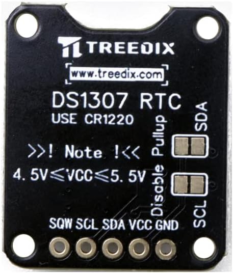
Figure 2: Top view of the DS1307 RTC board with pin labels.
The board dimensions are approximately 2.54 cm (1 inch) by 2.16 cm (0.85 inches).

Figure 3: DS1307 RTC board dimensions.
Pin Descriptions:
- GND: Ground connection.
- VCC: Power supply input (5V).
- SDA: I2C Serial Data Line.
- SCL: I2C Serial Clock Line.
- SQW: Square Wave Output pin. This pin can output a square wave at 1Hz, 4kHz, 8kHz, or 32kHz, configurable via software.
On-Board Features:
- CR1220 Battery Holder: For battery backup.
- Pull-up Resistors: The board includes built-in pull-up resistors for the I2C lines (SDA and SCL). There are jumpers to disable these pull-ups if your microcontroller or other I2C devices already provide them.
4. Setup and Connection
This section details the steps to set up your DS1307 RTC breakout board and connect it to a microcontroller, such as an Arduino.
4.1. Battery Installation
Before connecting the board, ensure the CR1220 battery is correctly installed in the battery holder. The positive (+) side of the battery should face upwards, matching the (+) marking on the holder.

Figure 4: DS1307 RTC board with CR1220 battery installed.
4.2. Wiring to Arduino
The DS1307 communicates via I2C, which typically uses two pins: SDA (Serial Data) and SCL (Serial Clock). For Arduino boards, these pins are usually:
- Arduino Uno/Nano/Mega: SDA is A4, SCL is A5.
- Arduino Due: SDA is 20, SCL is 21.
Follow these steps to connect the DS1307 to your Arduino:
- Connect the GND pin of the DS1307 to the GND pin on your Arduino.
- Connect the VCC pin of the DS1307 to the 5V pin on your Arduino.
- Connect the SDA pin of the DS1307 to the SDA pin (e.g., A4) on your Arduino.
- Connect the SCL pin of the DS1307 to the SCL pin (e.g., A5) on your Arduino.
- The SQW pin is optional and can be connected to a digital input pin on your Arduino if you wish to use the square wave output feature.
Ensure all connections are secure. The board is designed for plug-and-play use with standard PCB headers.
5. Operating Instructions
To operate the DS1307 RTC, you will need to use an I2C library for your microcontroller. For Arduino, the standard Wire library is commonly used, often in conjunction with a dedicated DS1307 library for easier time management.
5.1. Required Libraries
For Arduino, install a DS1307-specific library from the Arduino IDE's Library Manager (e.g., "RTClib" by Adafruit or "DS1307RTC" by Michael Margolis).
5.2. Setting the Time
Upon initial setup or after a prolonged power loss without battery backup, the RTC will need to be set to the current date and time. Most libraries provide functions to set the time using values from your computer's clock or manually specified values.
#include <Wire.h>
#include <RTClib.h>

RTC_DS1307 rtc;

void setup() {
  Serial.begin(9600);
  Wire.begin();

  if (! rtc.begin()) {
    Serial.println("Couldn't find RTC");
    while (1);
  }

  if (! rtc.isrunning()) {
    Serial.println("RTC is NOT running, let's set the time!");
    // Following line sets the RTC to the date & time this sketch was compiled
    rtc.adjust(DateTime(F(__DATE__), F(__TIME__)));
    // This line sets the RTC with an explicit date & time, for example:
    // rtc.adjust(DateTime(2023, 11, 30, 16, 30, 0));
  }
}

void loop() {
  // Your main code here
}
Example code snippet for setting time using RTClib.
5.3. Reading the Time
Once the time is set, you can read the current date and time from the RTC at any point in your program.
#include <Wire.h>
#include <RTClib.h>

RTC_DS1307 rtc;

void setup() {
  Serial.begin(9600);
  Wire.begin();

  if (! rtc.begin()) {
    Serial.println("Couldn't find RTC");
    while (1);
  }
}

void loop() {
  DateTime now = rtc.now();

  Serial.print(now.year(), DEC);
  Serial.print('/');
  Serial.print(now.month(), DEC);
  Serial.print('/');
  Serial.print(now.day(), DEC);
  Serial.print(" (");
  Serial.print(now.dayOfWeek(), DEC);
  Serial.print(") ");
  Serial.print(now.hour(), DEC);
  Serial.print(':');
  Serial.print(now.minute(), DEC);
  Serial.print(':');
  Serial.print(now.second(), DEC);
  Serial.println();

  delay(1000);
}
Example code snippet for reading time using RTClib.
5.4. Square Wave Output (SQW)
The DS1307 can generate a square wave output on the SQW pin. This feature can be enabled and configured via I2C commands to output frequencies of 1Hz, 4kHz, 8kHz, or 32kHz. Consult your chosen DS1307 library's documentation for specific functions to control the SQW pin.
5.5. Disabling I2C Pull-up Resistors
The Treedix DS1307 board includes on-board pull-up resistors for the I2C lines (SDA and SCL). In some advanced setups, especially when multiple I2C devices are connected or if your microcontroller already has strong internal pull-ups, you might need to disable the on-board pull-ups to avoid signal integrity issues. This can typically be done by cutting the traces on the small jumpers located near the SDA and SCL pins, as indicated on the board (labeled "Disable Pullup"). Exercise caution if performing this modification.
6. Maintenance
The DS1307 RTC module is generally maintenance-free, but the CR1220 battery will eventually need replacement.
6.1. Battery Replacement
The CR1220 lithium battery provides power to the RTC when the main power supply is off, preserving the time and date. The lifespan of the battery depends on usage and environmental factors. When the RTC starts losing time or fails to keep time during power outages, it's an indication that the battery needs replacement.
To replace the battery:
- Carefully remove the old CR1220 battery from its holder.
- Insert a new CR1220 3V lithium battery, ensuring the positive (+) side faces upwards.
- After replacing the battery, it is recommended to reset the time on the RTC as described in Section 5.2.
Note: Some users have reported that the included CR1220 batteries may have a shorter lifespan or lower voltage than expected. If you experience immediate timekeeping issues, consider replacing the battery with a new, high-quality CR1220 from a reputable manufacturer.
7. Troubleshooting
If you encounter issues with your Treedix DS1307 RTC module, consider the following troubleshooting steps:
- RTC Not Detected:
- Check all wiring connections (GND, VCC, SDA, SCL) for continuity and correct pin assignment.
- Ensure the Arduino's I2C pins are correctly identified (e.g., A4/A5 for Uno).
- Verify that the 5V power supply is stable.
- Confirm that the I2C library is correctly installed and included in your sketch.
- Run an I2C scanner sketch to confirm the DS1307's I2C address (typically 0x68).
- Time Not Keeping/Incorrect Time:
- Check if the CR1220 battery is correctly installed and has sufficient voltage (3V). Replace if necessary.
- Ensure the time was correctly set initially (refer to Section 5.2).
- Verify that the RTC is running (
rtc.isrunning()function in RTClib). If not, it needs to be set.
- I2C Communication Errors:
- If you have multiple I2C devices or long I2C lines, ensure the pull-up resistors are correctly configured (on-board or external). If experiencing issues, try disabling the on-board pull-ups if your microcontroller provides them.
8. Specifications
| Feature | Specification |
|---|---|
| Brand | Treedix |
| Model | DS1307 |
| Operating Voltage | 5V |
| Connectivity Technology | I2C |
| Timekeeping Accuracy | ±2 minutes/month (typical, without temperature compensation) |
| Battery Type | CR1220 3V Lithium (included) |
| Item Weight | 0.317 ounces (approx. per board) |
| Product Dimensions (LxWxH) | 1 x 0.85 x 0.06 inches (approx. per board) |
| Compatible Devices | Single-board computers, particularly Arduino |
| Included Components | Real-time clock breakout board, pin header, CR1220 battery |
9. Warranty and Support
For product support, technical assistance, or warranty inquiries, please refer to the Treedix official website or contact their customer service directly through the platform where the product was purchased. Please have your purchase details and product model number (DS1307) ready when contacting support.


