1. Introduction
This manual provides detailed instructions for the installation, operation, and maintenance of your ASUS Prime B650M-A AX Micro-ATX Motherboard. Designed to support AMD Ryzen 7000 series processors, this motherboard offers robust performance, comprehensive cooling, and extensive connectivity options for daily users and PC builders.
Please read this manual thoroughly before beginning installation to ensure proper setup and to maximize the performance and longevity of your system.
2. Package Contents
Verify that all items listed below are present in your motherboard package. If any item is missing or damaged, contact your retailer.
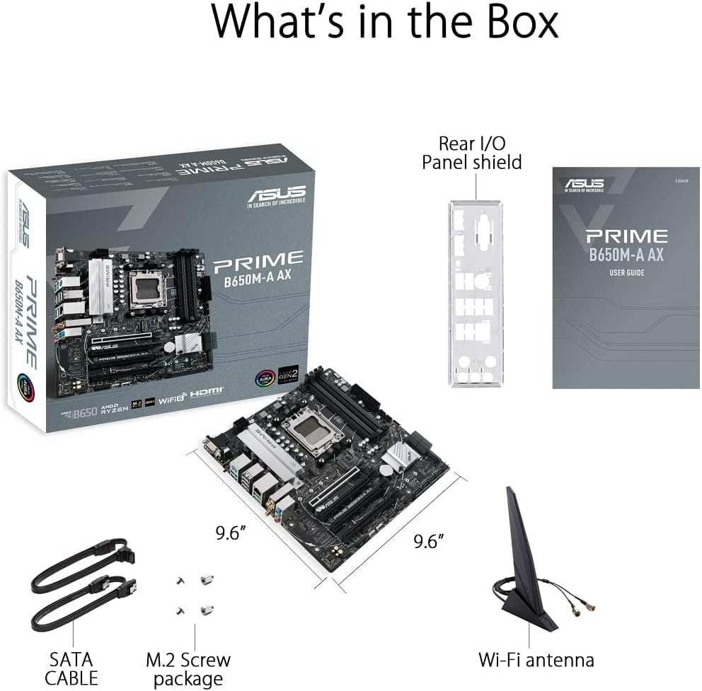
Figure 2.1: Contents of the ASUS Prime B650M-A AX Motherboard package.
- ASUS Prime B650M-A AX Motherboard
- Rear I/O Panel Shield
- User Guide (Printed Manual)
- SATA Cables (x2)
- M.2 Screw Package
- Wi-Fi Antenna
3. Product Overview and Features
The ASUS Prime B650M-A AX motherboard is designed to provide a stable and high-performance foundation for your PC build. Key features include:
3.1. Component Layout and Power Delivery

Figure 3.1: Motherboard layout highlighting power delivery and cooling components.
- AMD AM5 Socket: Ready for AMD Ryzen 7000 Series Desktop Processors.
- Robust Power Delivery: Features a comprehensive VRM heatsink and thermal pads for stable power delivery to the CPU.
- Comprehensive Cooling: Includes VRM heatsink, PCH heatsink, hybrid fan headers, and Fan Xpert 2+ for efficient thermal management.
3.2. Memory and Storage
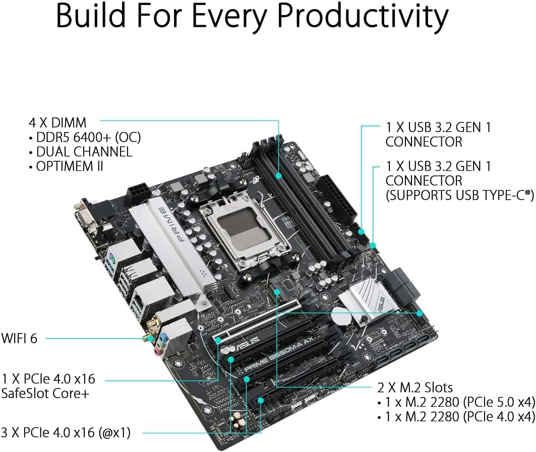
Figure 3.2: Motherboard layout highlighting memory and storage options.
- DDR5 Support: Four DIMM slots supporting DDR5 memory with ASUS OptiMem II for improved memory overclocking and signal integrity.
- PCIe 5.0 M.2: One PCIe 5.0 M.2 slot for ultra-fast storage, alongside another PCIe 4.0 M.2 slot.
- PCIe Expansion: One PCIe 4.0 x16 SafeSlot Core+ and three PCIe 4.0 x1 slots for expansion cards.
3.3. Connectivity

Figure 3.3: Rear I/O Panel connectivity options.
- Wi-Fi 6: Integrated Wi-Fi 6 for high-speed wireless networking.
- 2.5Gb LAN: Realtek 2.5Gb Ethernet for fast wired network connections.
- USB Ports: Multiple USB 3.2 Gen 2 ports, USB 3.2 Gen 1 ports (including front USB 3.2 Gen 1 Type-C®), and USB 2.0 ports.
- Video Outputs: DisplayPort, HDMI, and VGA for display connectivity.
- BIOS FlashBack™: Dedicated button for easy BIOS updates without a CPU or memory installed.
3.4. Personalization and Audio
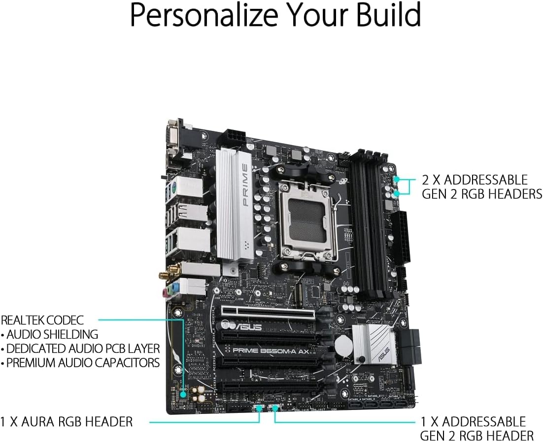
Figure 3.4: Motherboard layout highlighting audio and RGB features.
- Aura Sync RGB Lighting: Onboard Addressable Gen 2 headers and an Aura RGB header for RGB LED strips, easily synced with Aura Sync-capable hardware.
- Enhanced Audio: Features Realtek Codec, audio shielding, a dedicated audio PCB layer, and premium audio capacitors for high-quality sound.
4. Setup and Installation
Before you begin, ensure your system is powered off and unplugged from the wall outlet. Always handle the motherboard by its edges to prevent damage from static electricity.
- Prepare the Chassis: Install the I/O shield into your PC case. Ensure proper standoffs are installed in the chassis for the Micro-ATX form factor.
- Install the Motherboard: Carefully place the motherboard into the chassis, aligning the screw holes with the standoffs. Secure the motherboard with screws.
- Install the CPU: Open the CPU socket lever, align the CPU with the socket (triangle mark on CPU to triangle mark on socket), gently place the CPU, and close the lever to secure it.
- Install the CPU Cooler: Mount your CPU cooler according to its manufacturer's instructions. Ensure thermal paste is applied.
- Install Memory (RAM): Open the clips on the DIMM slots. Align the memory module's notch with the slot's key. Press down firmly on both ends until the clips snap into place. For dual-channel operation, refer to your motherboard's specific manual for recommended slot configurations.
- Install M.2 SSDs: Insert the M.2 SSD into the M.2 slot at an angle, then gently push it down and secure it with the provided M.2 screw.
- Install Graphics Card (Optional): Insert your graphics card into the PCIe 4.0 x16 slot (SafeSlot Core+). Ensure it clicks into place and secure it with a screw to the chassis.
- Connect Power Cables: Connect the 24-pin ATX power connector and the 8-pin CPU power connector from your power supply to the motherboard.
- Connect Front Panel Cables: Connect the power button, reset button, HDD LED, power LED, and front panel USB/audio cables to their respective headers on the motherboard. Refer to the motherboard manual for exact pin layouts.
- Connect Storage Drives: Connect SATA data cables from your SATA SSDs/HDDs to the SATA ports on the motherboard, and connect power cables from your power supply to the drives.
- Connect Wi-Fi Antenna: Screw the included Wi-Fi antenna onto the rear I/O panel connectors.
5. Operating Instructions
Once all components are installed and connected, you can power on your system.
- First Boot: After powering on, the system will typically enter the BIOS/UEFI setup utility.
- BIOS/UEFI Setup:
- Press DEL or F2 during POST (Power-On Self-Test) to enter the BIOS/UEFI setup.
- Configure boot order, enable XMP/EXPO for memory, and set other system parameters as needed.
- Save changes and exit BIOS to proceed with operating system installation.
- Operating System Installation: Insert your Windows or Linux installation media and follow the on-screen prompts to install your preferred operating system.
- Driver Installation: After OS installation, install the latest drivers for your motherboard (chipset, LAN, Wi-Fi, audio, etc.) from the ASUS support website to ensure optimal performance and stability.
6. Maintenance
Regular maintenance helps ensure the longevity and optimal performance of your motherboard.
- Dust Removal: Periodically clean dust from the motherboard and components using compressed air. Ensure the system is powered off and unplugged before cleaning.
- BIOS Updates: Check the ASUS support website for the latest BIOS updates. Updating the BIOS can improve compatibility, stability, and performance. Use the BIOS FlashBack™ feature for convenient updates.
- Driver Updates: Keep your motherboard drivers updated to ensure compatibility with new software and hardware, and to benefit from performance improvements and bug fixes.
- Physical Inspection: Occasionally inspect the motherboard for any loose connections, damaged components, or signs of overheating.
7. Troubleshooting
This section addresses common issues you might encounter.
| Problem | Possible Cause | Solution |
|---|---|---|
| System does not power on. | Loose power cables, faulty power supply, incorrect front panel connections. | Check 24-pin ATX and 8-pin CPU power connections. Verify front panel power switch connection. Test power supply. |
| No display on monitor. | Incorrect video cable connection, faulty graphics card/integrated graphics, loose RAM. | Ensure monitor cable is securely connected to the correct port. Reseat graphics card and RAM modules. Test with integrated graphics if available. |
| System reboots unexpectedly. | Overheating, unstable power, faulty RAM, driver issues. | Check CPU/GPU temperatures. Ensure adequate cooling. Test RAM with diagnostic tools. Update drivers. |
| Wi-Fi/LAN not working. | Missing drivers, antenna not connected (Wi-Fi), loose Ethernet cable (LAN). | Install/update Wi-Fi and LAN drivers from ASUS website. Ensure Wi-Fi antenna is securely attached. Check Ethernet cable connection. |
For more detailed troubleshooting, refer to the comprehensive user manual available on the ASUS support website or consult the User Guide (PDF).
8. Specifications
Below are the key technical specifications for the ASUS Prime B650M-A AX Motherboard:
| Feature | Detail |
|---|---|
| Brand | ASUS |
| Model Name | PRIME B650M-A AX |
| CPU Socket | Socket AM5 |
| Compatible Processors | AMD Ryzen 7000 series |
| Chipset Type | AMD B650 |
| RAM Memory Technology | DDR5 |
| Memory Speed | Up to 6400 MHz (OC) |
| Memory Storage Capacity (Max) | 128 GB |
| Wireless Type | 802.11ax (Wi-Fi 6) |
| LAN | Realtek 2.5Gb Ethernet |
| Product Dimensions | 10.8 x 10.9 x 2.7 inches |
| Item Weight | 2.9 pounds |
| Voltage | 12 Volts |
| First Available Date | October 12, 2022 |
9. Warranty and Support
ASUS provides a limited warranty for its products. For specific warranty terms and conditions, please refer to the warranty card included with your product or visit the official ASUS support website.
For technical support, driver downloads, BIOS updates, and further documentation, please visit the official ASUS support website. You can also refer to the comprehensive User Guide (PDF) for detailed information.
ASUS Support Website: https://www.asus.com/support/