WeePro Vpro850L
WeePro Vpro850L Digital Multimeter User Manual
Model: Vpro850L
1. Introduction
The WeePro Vpro850L Digital Multimeter is a versatile and reliable tool designed for both household and industrial electrical testing. It functions as an AC/DC Voltmeter, Ohm Volt Amp Tester, Electric Ohmmeter, Diode, Resistance, and Audible Continuity Detector. Its robust design and user-friendly features make it suitable for a wide range of applications, including testing household outlets, fuses, batteries (including vehicle batteries), automotive circuit troubleshooting, and general electronics testing.
2. Safety Information
WARNING: Always exercise extreme caution when working with electrical circuits. Improper use of this multimeter can result in injury or death.
- Read and understand all instructions before using the multimeter.
- Do not exceed the maximum input values for any function.
- Ensure test leads are properly connected and the function switch is set to the correct range before making measurements.
- Inspect test leads for damage before each use. Do not use if insulation is damaged.
- Avoid touching exposed wiring or circuit components while testing.
- Do not use the multimeter if it appears damaged or is not operating correctly.
- Replace the battery when the low battery indicator appears to ensure accurate readings.
3. What's in the Box
- 1 x WeePro Vpro850L Digital Multimeter
- 1 x 9V Battery (included and pre-installed)
- 2 x Test Leads (80cm)
- 2 x Alligator Clips
- 1 x User Manual
4. Product Overview

Figure 1: Front view of the WeePro Vpro850L Digital Multimeter with key components labeled. This includes the LCD, Backlight Button, Hold Button, Range Switch, hFE Socket, VΩmA Jack, COM Jack, and 10A Jack.

Figure 2: The multimeter is shown with its insulated rubber case and integrated kickstand, designed for enhanced grip, easier reading, and maximum safety.
5. Setup
5.1 Battery Installation
The 9V battery is typically pre-installed. If replacement is needed:
- Ensure the multimeter is turned OFF.
- Locate the battery compartment on the back of the unit.
- Use a small Phillips head screwdriver to remove the screw securing the battery cover.
- Carefully remove the cover.
- Connect the new 9V battery to the battery clips, observing correct polarity.
- Place the battery inside the compartment and replace the cover, securing it with the screw.
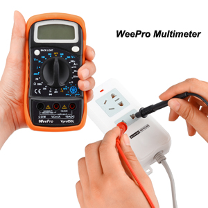
Figure 3: A standard 9V battery, required for powering the multimeter.
5.2 Connecting Test Leads and Alligator Clips
The multimeter comes with two test leads (red and black) and two alligator clips. The alligator clips can be attached to the test leads for hands-free testing.
- Insert the black test lead into the "COM" (Common) jack.
- Insert the red test lead into the "VΩmA" jack for most voltage, resistance, and small current measurements. For high current (up to 10A) measurements, insert the red test lead into the "10ADC" jack.
- To attach alligator clips, slide them over the metal probes of the test leads until they are securely connected.
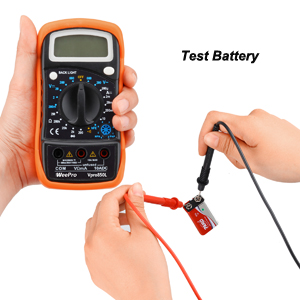
Figure 4: Proper connection of red and black test leads to the multimeter's input jacks.

Figure 5: Alligator clips provide a secure connection for hands-free testing.
6. Operating Instructions
The Vpro850L features a large, backlit LCD display for clear readings and a rotary switch to select measurement functions.
6.1 Turning On/Off and Backlight
- To turn on the multimeter, rotate the function switch from "OFF" to any desired measurement function.
- To turn off, rotate the function switch back to "OFF".
- Press the "BACK LIGHT" button to illuminate the display for better visibility in low-light conditions. Press again to turn off.

Figure 6: The backlight feature enhances readability of the LCD display.
6.2 Data Hold Function
The "HOLD" button allows you to freeze the current reading on the display.
- While taking a measurement, press the "HOLD" button to capture and display the current value.
- Press the "HOLD" button again to release the reading and return to live measurement.

Figure 7: The Data Hold function allows users to retain a reading on the screen after removing the probes.
6.3 Measuring Voltage (AC/DC)
- Connect the black test lead to the "COM" jack and the red test lead to the "VΩmA" jack.
- Rotate the function switch to the desired AC Voltage (V~) or DC Voltage (V-) range. Start with the highest range if the voltage is unknown.
- Connect the test probes across the circuit or component to be measured.
- Read the voltage value on the LCD display.
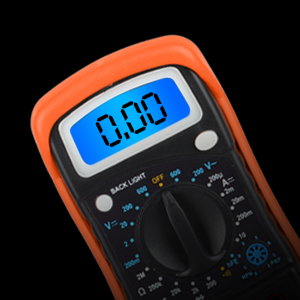
Figure 8: Example of testing an electrical outlet for voltage.
6.4 Measuring Resistance (Ohms)
- Connect the black test lead to the "COM" jack and the red test lead to the "VΩmA" jack.
- Rotate the function switch to the desired Ohm (Ω) range.
- Connect the test probes across the component to be measured. Ensure the circuit is de-energized before measuring resistance.
- Read the resistance value on the LCD display.
6.5 Continuity Test
The continuity test checks for a complete circuit path and provides an audible buzzer if resistance is low.
- Connect the black test lead to the "COM" jack and the red test lead to the "VΩmA" jack.
- Rotate the function switch to the continuity ())) position.
- Touch the test probes across the circuit or component.
- If the resistance is lower than 30Ω±20Ω, the buzzer will sound, indicating continuity.

Figure 9: Performing a continuity test. The multimeter will emit a buzzing sound if continuity is detected.
6.6 Diode Test
- Connect the black test lead to the "COM" jack and the red test lead to the "VΩmA" jack.
- Rotate the function switch to the Diode ( ▲) position.
- Connect the red probe to the anode and the black probe to the cathode of the diode.
- Read the forward voltage drop on the display. Reverse the probes; an open circuit (OL) reading indicates a good diode.
6.7 Measuring Current (DC)
- Connect the black test lead to the "COM" jack. For currents up to 200mA, connect the red test lead to the "VΩmA" jack. For currents up to 10A, connect the red test lead to the "10ADC" jack.
- Rotate the function switch to the desired DC Current (A-) range.
- Break the circuit and connect the multimeter in series with the circuit to be measured.
- Read the current value on the LCD display.
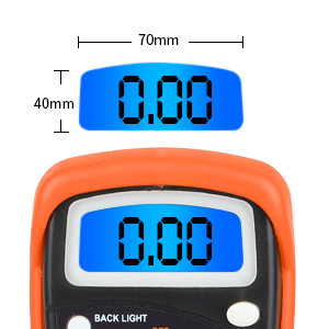
Figure 10: The multimeter can be used to test the voltage of various batteries, such as a 9V battery.
7. Maintenance
7.1 Cleaning
To clean the multimeter, wipe the case with a damp cloth and mild detergent. Do not use abrasives or solvents. Ensure the device is off and disconnected from any power source before cleaning.
7.2 Storage
When not in use for extended periods, remove the battery to prevent leakage and store the multimeter in a cool, dry place away from direct sunlight and extreme temperatures.
8. Troubleshooting
- No Display/Faint Display: Check the 9V battery. Replace if low or dead. Ensure the function switch is not in the "OFF" position.
- "1" or "OL" Indication: This indicates an overload or out-of-range measurement. Select a higher range or ensure the circuit is within the multimeter's capabilities. For continuity/diode tests, it indicates an open circuit.
- Inaccurate Readings: Check battery level. Ensure test leads are fully inserted and not damaged. Verify the correct function and range are selected for the measurement.
- No Continuity Buzzer: Ensure the function switch is set to the continuity position. Check if the resistance is above the threshold (30Ω±20Ω) for the buzzer to activate.
9. Specifications
| Feature | Specification |
|---|---|
| Model Number | Vpro850L |
| Product Dimensions | 5.7 x 2.9 x 1.4 inches |
| Item Weight | 6.4 ounces |
| Power Source | Battery Powered (1 x 9V battery included) |
| Display | 3 ½ digits (1999 count) 0.6” Backlit LCD |
| Sampling Speed | 2 times per second |
| Over-load Indication | "1" displayed |
| Low Battery Indication | Displayed when battery power is low |
| Continuity Buzzer Threshold | Resistance lower than 30Ω±20Ω |
| Protection | PTC protection circuit for Resistance and frequency measurement |
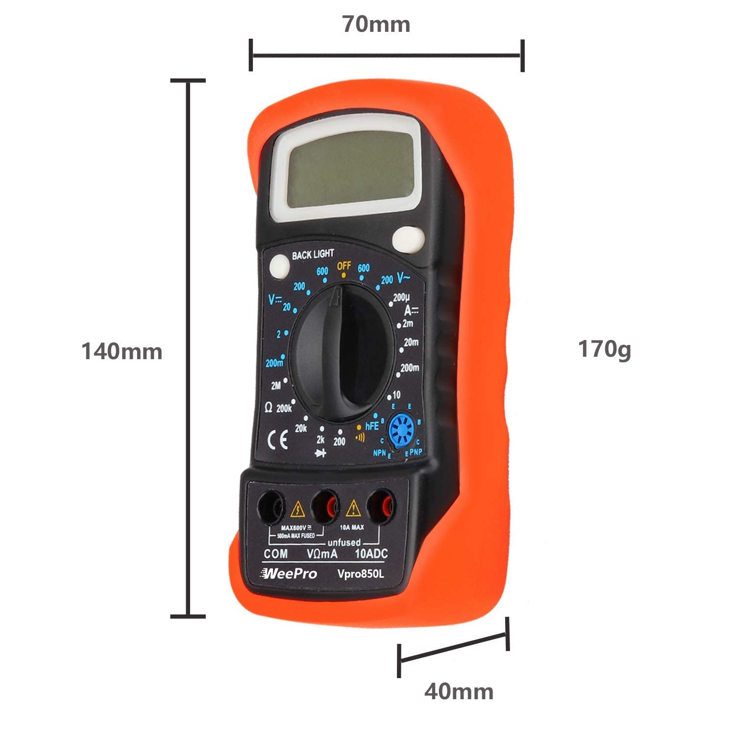
Figure 11: Physical dimensions of the WeePro Vpro850L Digital Multimeter.
10. Warranty and Support
All sales of the WeePro Vpro850L Digital Multimeter come with a 90-day return refund guarantee, a 10-year warranty, and lifetime support provided by WeePro. For any inquiries or support needs, please contact WeePro customer service.
Ask a question about this manual
Ask about setup, troubleshooting, compatibility, parts, safety, or missing instructions. Manuals+ will review the question and use this page’s manual context to help answer it.