Greluma ZL501LUM
Greluma DC 12V Temperature Controller Module User Manual
Model: ZL501LUM
Brand: Greluma
1. Product Overview
The Greluma DC 12V Temperature Controller Module is a versatile electronic thermostat designed for precise temperature regulation. It features a digital display, an NTC waterproof probe, and a relay output for controlling various heating or cooling devices. This module is ideal for applications requiring accurate temperature monitoring and control, such as scientific planting, incubation, and HVAC systems.
- Integrated sensor inputs, control buttons, LED display, and relay for comprehensive control.
- Wide temperature measurement range: -50°C to 110°C with 0.1°C control accuracy.
- Bright 3-bit LED display for clear temperature readings.
- Microprocessor-controlled output ensures high precision and excellent temperature resolution.
- Waterproof NTC probe allows for temperature control of liquids.
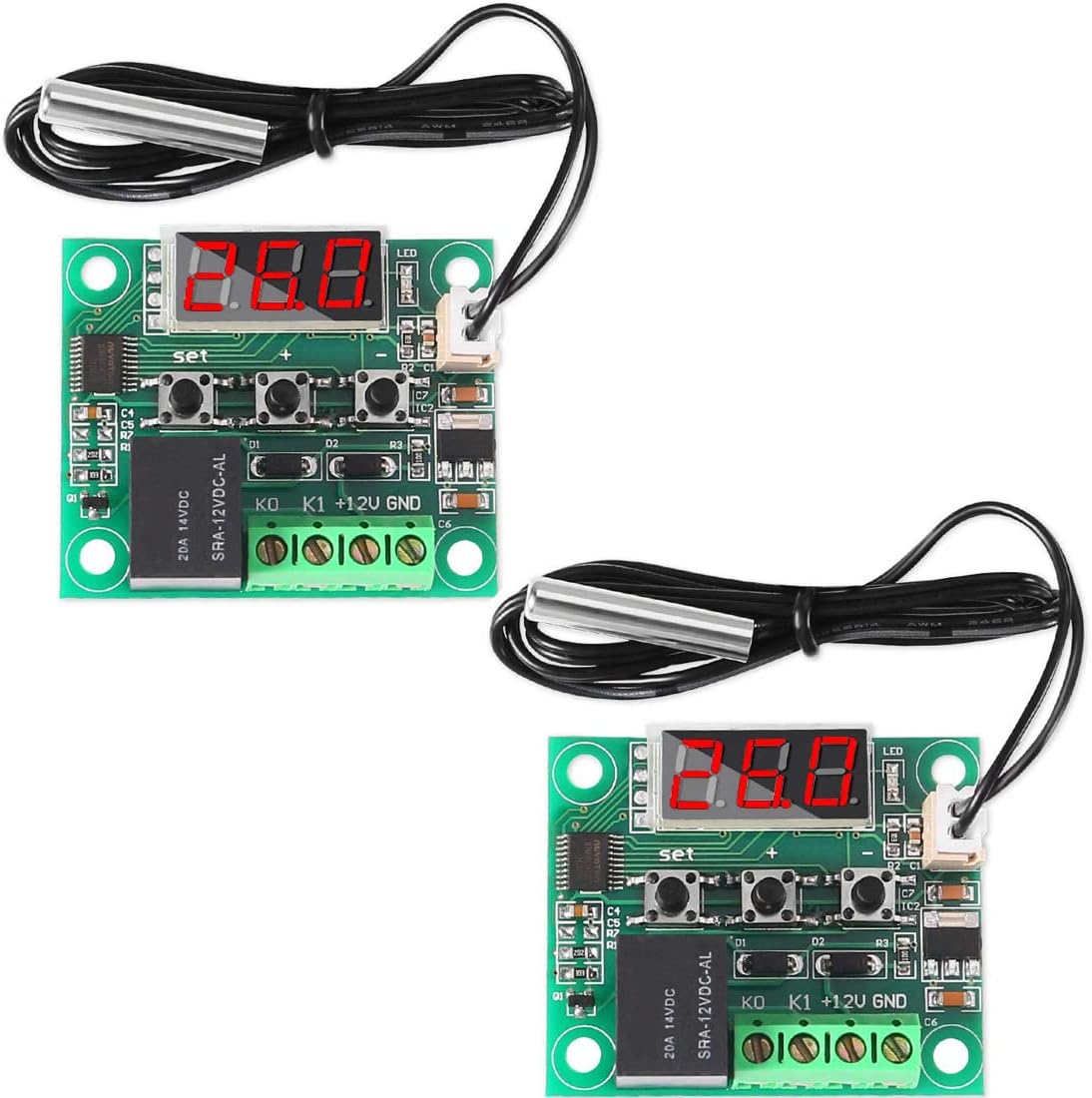
Figure 1.1: Two Greluma DC 12V Temperature Controller Modules.
2. Specifications
| Parameter | Value |
|---|---|
| Model Number | ZL501LUM |
| Dimensions (L x W x H) | 48.5 x 40 x 15.8 mm |
| Temperature Control Mode | ON/OFF |
| Temperature Range | -50°C to 110°C |
| Resolution (0.1°C) | -9.9°C to 99.9°C |
| Resolution (1°C) | Other temperature segments |
| Control Accuracy | 0.1°C |
| Hysteresis Accuracy | 0.1°C |
| Refresh Rate | 0.5 seconds |
| Power Supply Voltage | DC 12V |
| Static Current | < 35mA |
| Attraction Current | < 65mA |
| Output Voltage | DC 12V |
| Output Power | 20A Relay |
| Measurement Input | NTC (10K 0.5%) waterproof sensor |
| Environmental Requirements | -10°C to 60°C; Humidity: 20% to 85% |
| Item Weight | 30 grams |
| Included Components | 2 x 12V DC Digital Temperature Control Boards |
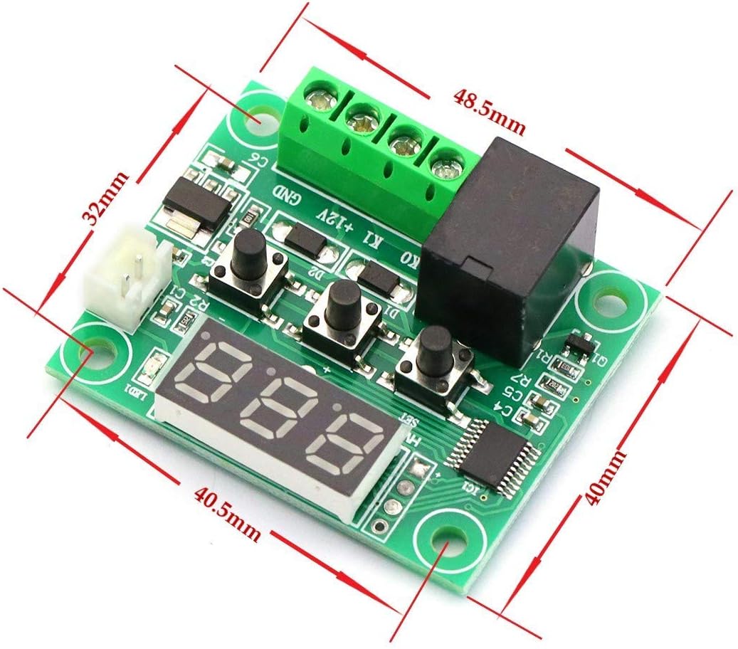
Figure 2.1: Module dimensions (48.5mm x 40mm x 15.8mm).

Figure 2.2: Key components of the temperature controller module, including the digital display, indicator LED, sensor interface, and reliable relay.
3. Setup and Wiring
Before connecting the module, ensure all power sources are disconnected. The module operates on a DC 12V power supply. Carefully follow the wiring diagrams below for proper installation.
3.1. Power and Sensor Connection
- Connect the DC 12V power supply to the
+12VandGNDterminals on the module. - Connect the NTC waterproof sensor to the
KOandK1terminals. The sensor is non-polar, so connection order does not matter.
3.2. Load Connection
The module's relay output can control various loads (e.g., heating elements, cooling fans, lights). The relay acts as a switch. Connect your load to the relay terminals as shown in the diagrams.

Figure 3.1: Example wiring diagrams for connecting a 220V AC load (top) and a DC load (bottom) to the module.
Important: Ensure correct polarity for DC loads and proper live/neutral connections for AC loads. If you are unsure about electrical wiring, consult a qualified electrician.
4. Operating Instructions
Once the module is powered on and connected, the current measured temperature will be displayed on the LED screen.
4.1. Setting the Desired Temperature
- Press the "SET" button once. The displayed temperature will start flashing.
- Use the "+" or "-" buttons to adjust the desired temperature value. Press and hold for rapid adjustment.
- Press the "SET" button again to confirm the setting and exit. The module will now operate based on the set temperature.

Figure 4.1: Button functions: SET (used to set switching), + (increase temperature), - (reduce temperature).
4.2. LED Indicator Status
- LED Off: The relay is off (open circuit).
- LED On: The relay is closed (active), supplying power to the connected load.
4.3. Digital Display Error Codes
- "LL": Indicates an open circuit or disconnected temperature sensor. Check the sensor's connection to the
KOandK1terminals. Ensure the sensor cable is not damaged. - "HH": Indicates the measured temperature is outside the module's operating range (-50°C to 110°C). Verify the environment temperature and ensure the sensor is correctly placed. The relay will be forcibly disconnected in this state.
- "--": Indicates a high-temperature alarm. Check your system for overheating. Review your P6 setting (High Temperature Alarm) and adjust if necessary.
4.4. Advanced Parameter Settings (P0-P6)
To access advanced settings, long press the "SET" button until the display shows "P0".
- While in the parameter menu, use the "+" or "-" buttons to navigate between parameters P0 to P6.
- To enter a specific parameter's setting, press the "SET" button once.
- Use "+" or "-" to change the value of the selected parameter.
- Press "SET" again to confirm the value and return to the P-menu.
- To exit the advanced settings menu, long press "SET" or wait for 10 seconds without any button presses.
| Code | Description | Setting Range | Factory Settings |
|---|---|---|---|
| P0 | Cooling/Heating Mode | C/H | C (Cooling) |
| P1 | Hysteresis Setting | 0.1-15 | 2 |
| P2 | Set Upper Temperature Limit | 110°C | 110 |
| P3 | Set Lower Temperature Limit | -50°C | -50 |
| P4 | Temperature Calibration | -7°C ~ 7°C | 0 |
| P5 | Delay Start Time | 0-600S | 0 |
| P6 | High Temperature Alarm | 0-110°C | OFF |
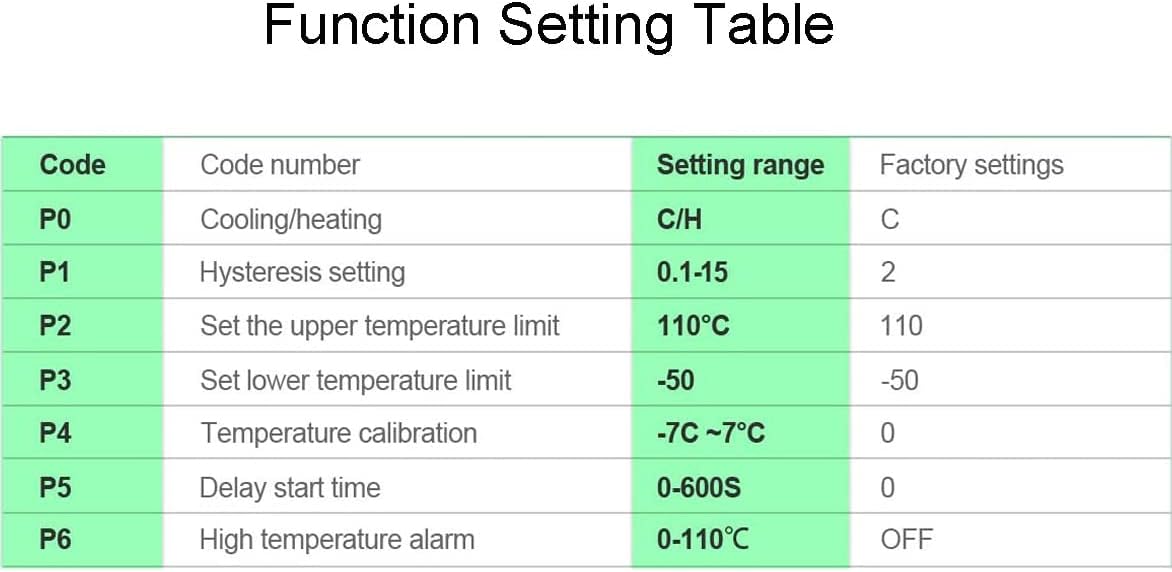
Figure 4.2: Detailed table of advanced function settings and their ranges.
5. Troubleshooting
This section provides solutions to common issues you might encounter with your Greluma Temperature Controller Module.
- Display shows "LL": This indicates an open circuit or disconnected temperature sensor. Check the sensor's connection to the
KOandK1terminals. Ensure the sensor cable is not damaged. - Display shows "HH": The measured temperature is outside the module's operating range (-50°C to 110°C). Verify the environment temperature and ensure the sensor is correctly placed. The relay will be forcibly disconnected in this state.
- Display shows "--": This is a high-temperature alarm. Check your system for overheating. Review your P6 setting (High Temperature Alarm) and adjust if necessary.
- Module not powering on: Check the DC 12V power supply connection. Ensure correct polarity and that the power supply is providing the correct voltage.
- Relay not activating/deactivating: Verify your set temperature and the current measured temperature. Check the P0 setting (Cooling/Heating Mode) to ensure it matches your application. Also, check the hysteresis setting (P1). Ensure the load is correctly wired to the relay terminals.
- Inaccurate temperature reading: If the displayed temperature does not match a known accurate thermometer, you can use the P4 setting (Temperature Calibration) to adjust the reading.
6. Maintenance
The Greluma Temperature Controller Module is designed for low maintenance. Follow these general guidelines to ensure its longevity and optimal performance:
- Keep Clean: Regularly clean the module with a soft, dry cloth to prevent dust accumulation, especially on the display and buttons.
- Avoid Moisture: Although the NTC probe is waterproof, the main module is not. Ensure the module itself is kept in a dry environment, within the specified humidity range (20% to 85%).
- Temperature Environment: Operate the module within its specified environmental temperature range (-10°C to 60°C) to prevent damage.
- Secure Connections: Periodically check all wiring connections to ensure they are secure and free from corrosion. Loose connections can lead to erratic behavior or damage.
- Sensor Care: Handle the NTC probe carefully. Avoid bending the cable sharply or subjecting the probe to excessive physical stress.
7. Warranty and Support
Greluma products are manufactured to high-quality standards. For specific warranty information, please refer to the documentation provided with your purchase or contact your retailer. For technical support or inquiries, please reach out to the seller or manufacturer through the platform where the product was purchased.
For further assistance, you may visit the Greluma brand page or contact customer service via the Amazon platform.
8. Applications
The Greluma DC 12V Temperature Controller Module is suitable for a wide range of applications requiring precise temperature control, including but not limited to:
- Scientific planting and greenhouse temperature regulation.
- Incubation temperature control for eggs.
- HVAC system control.
- Refrigeration and heating systems.
- Industrial control and automation.
- DIY projects requiring temperature management.

Figure 8.1: Examples of module applications: scientific planting and incubation temperature control.
no relevant documents
Ask a question about this manual
Ask about setup, troubleshooting, compatibility, parts, safety, or missing instructions. Manuals+ will review the question and use this page’s manual context to help answer it.