1. Introduction
The Eujgoov DCP 10 Generator Controller Module is a smart power management system designed to enhance the power quality and automation level of generator sets. It features an LCD display and supports a wide input voltage range of 8-35V. This manual provides essential information for the proper installation, operation, and maintenance of your DCP 10 controller.
2. Product Overview
The DCP 10 controller integrates metering, control, display monitoring, protection, and fault condition reporting via its LCD and LED indicators. It is a crucial component for efficient generator set management.
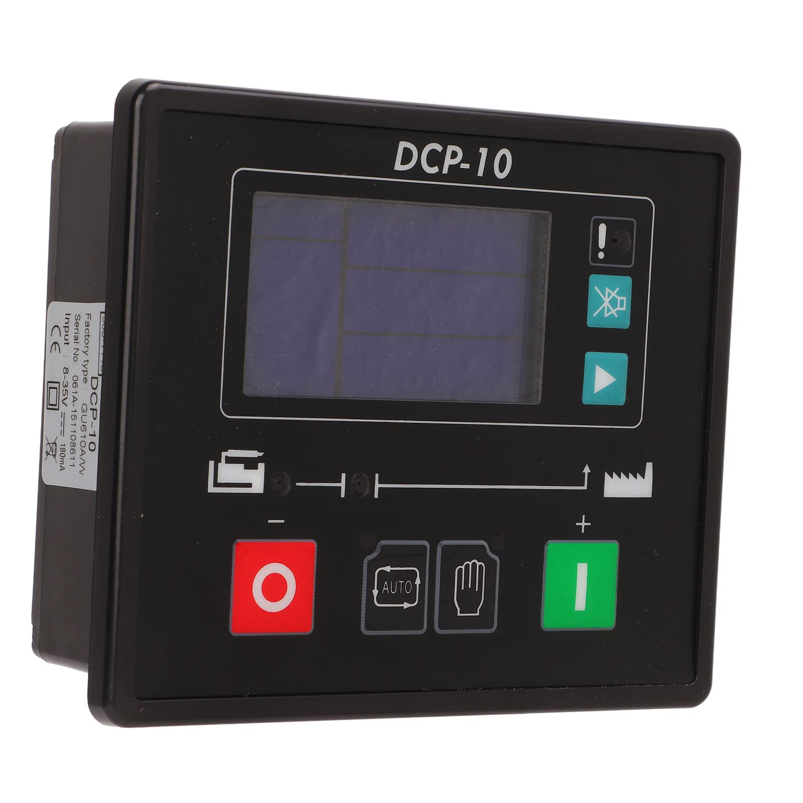
Figure 2.1: Front view of the DCP 10 Generator Controller Module, showing the LCD screen and control buttons.
Key Features:
- Performance Improvement: Enhances the power quality and automation level of the generator set.
- Self-Starting Control: Supports local manual control and remote control via external lines.
- Multi-Functionality: Includes automatic power on/off, data measurement, alarm functions, and three remote capabilities.
- Large LCD Screen: Features a clear LCD display with both Chinese and English interface options for ease of use.
- Integrated System: Combines metering, control, display monitoring, protection, operating status, and fault condition reporting.
3. Package Contents
Upon unpacking, please verify that all items listed below are included in your package:
- 1 x Generator Controller (DCP 10)
- 1 x User Manual (this document)
- 3 x Connection Terminals
- 2 x Mounting Accessories
4. Setup and Installation
Proper installation is crucial for the safe and effective operation of the DCP 10 controller. Ensure all connections are secure and correctly wired.
4.1 Wiring Connections
The controller can be connected to the starter battery to control the device locally. Carefully connect the control lines to the screen terminals as per the wiring diagram provided on the back of the unit.
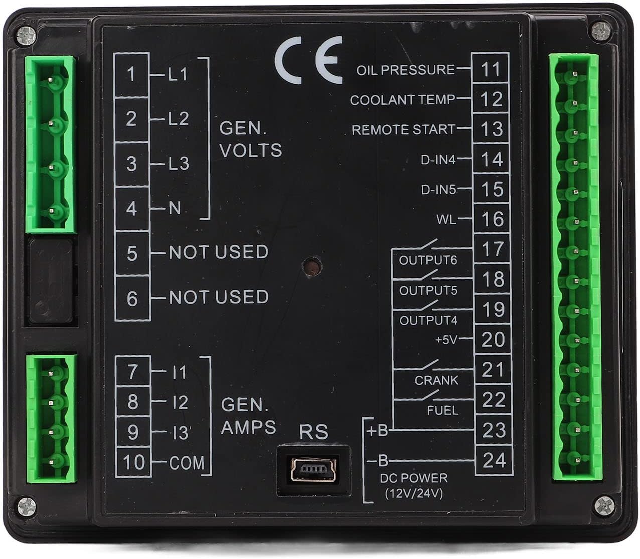
Figure 4.1: Back view of the DCP 10 Controller, illustrating the various input and output terminals for generator volts, amps, oil pressure, coolant temp, remote start, and DC power.
Refer to the detailed terminal labels on the back of the controller for specific connections:
- L1, L2, L3, N: Generator Voltage Inputs
- I1, I2, I3, COM: Generator Amperage Inputs
- Oil Pressure, Coolant Temp, Remote Start: Sensor and control inputs.
- D-IN4, D-IN5, WL: Digital inputs and warning lamp output.
- OUTPUT4, OUTPUT5, OUTPUT6: Configurable outputs.
- +5V: Auxiliary power output.
- CRANK, FUEL: Engine control outputs.
- +B, -B: DC Power input (12V/24V).

Figure 4.2: Close-up of the green pluggable connection terminals, facilitating easy and secure wiring.
4.2 Mounting
Use the provided mounting accessories to secure the controller in a suitable location, ensuring it is protected from excessive vibration, moisture, and extreme temperatures. Ensure adequate space for wiring and ventilation.
5. Operating Instructions
The DCP 10 controller offers intuitive operation through its LCD screen and control buttons.
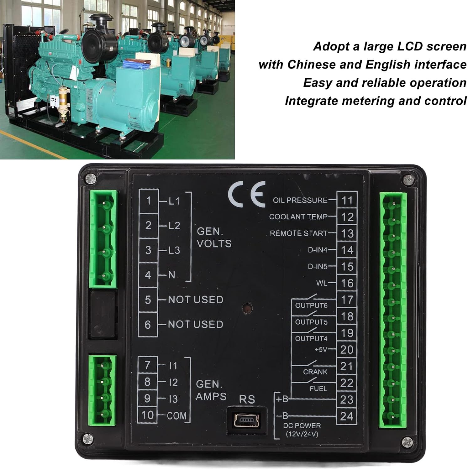
Figure 5.1: The DCP 10 controller features a large LCD screen with both Chinese and English interface options, designed for easy and reliable operation, integrating metering and control functions.
5.1 Basic Operation
- Power On/Off: The controller supports automatic power on and off functions. Manual control buttons are also available on the front panel.
- Data Measurement: The LCD screen displays various operational data, including generator voltage, amperage, and other monitored parameters.
- Alarm Functions: The system provides alarm indications for fault conditions, ensuring timely awareness of issues.
- Remote Control: The controller supports remote control capabilities through external signal lines, allowing for flexible management.
5.2 Navigating the LCD Display
Use the navigation buttons adjacent to the LCD screen to cycle through different display modes and view various parameters. The intuitive interface allows for easy monitoring of operating status and fault conditions.
6. Maintenance
To ensure the longevity and reliable performance of your DCP 10 controller, follow these general maintenance guidelines:
- Regular Cleaning: Keep the controller's exterior clean and free from dust and debris. Use a soft, dry cloth for cleaning.
- Connection Checks: Periodically inspect all wiring connections to ensure they are secure and free from corrosion.
- Environmental Protection: Ensure the controller remains within its specified operating environment (temperature, humidity) to prevent damage.
- Firmware Updates: Check the manufacturer's website for any available firmware updates that may improve performance or add features.
7. Troubleshooting
If you encounter issues with your DCP 10 controller, consider the following basic troubleshooting steps:
- No Power/Display: Verify the DC power input connections (+B, -B) and ensure the battery voltage is within the 8-35V range. Check for blown fuses in the power supply line.
- Incorrect Readings: Confirm that all sensor and generator input wiring (L1-N, I1-COM) are correctly connected and calibrated according to your generator's specifications.
- Alarm Activation: Identify the specific alarm code or message displayed on the LCD. Refer to the generator set's manual or the controller's advanced documentation for detailed alarm explanations and corrective actions.
- Remote Control Issues: Check the external signal line connections for remote control functionality. Ensure the external device is properly configured.
For persistent issues, contact Eujgoov customer support or a qualified technician.
8. Specifications
| Parameter | Value |
|---|---|
| Input Voltage Range | 8-35V |
| Input Current | 180mA |
| Item Weight | 12.3 ounces (approx. 348.7 grams) |
| Package Dimensions | 6.3 x 4.33 x 1.97 inches (approx. 16 x 11 x 5 cm) |
| Manufacturer | Eujgoov |
| Batteries Required | No |
9. Warranty and Support
Specific warranty information for the Eujgoov DCP 10 Generator Controller Module is not provided in this manual. Please refer to the product packaging, your purchase documentation, or contact the retailer or manufacturer directly for warranty details and technical support.


