1. Introduction
The CNCTOPBAOS V5 NPN NO 3D Touch Probe Edge Finder is a precision tool designed for CNC milling machines. It enables accurate and efficient execution of tasks such as quick centering, edge finding, center finding, and shape measurement on workpieces.

Figure 1: CNCTOPBAOS V5 NPN NO 3D Touch Probe Edge Finder
2. Product Features
- Functionality: The three-coordinate probe facilitates quick centering, edge finding, center finding, and shape measurement by connecting to the CNC system.
- Software Compatibility: Compatible with various control panels, including GRBL and Mach3.
- Repeatability Accuracy: Achieves a repeatability accuracy of 0.01 mm (0.0004 inches).
- Wiring: Features an NPN-NO 3-wire configuration:
Red: VCC / DC5-24V power
Yellow: IO / Signal Output
Black: GND / DCM - Indicator Light: Displays a green light when powered on and a red light after triggering.
- Probe Body Material: Constructed from fine frosted black oxidized aluminum alloy with a flat surface anti-roll design.
- Stylus Material: The probe tip/stylus is machined from stainless steel, and the ball head is made of wear-resistant tungsten steel.
- Concentricity: Factory-tuned to within 0.05mm. User adjustment may be required after installation.
- Chuck Requirement: For optimal performance and concentricity, use ER11 spring chucks of AAA or above accuracy.
3. Package Contents
Verify that all items are present in the package:
- 1x 3D Touch Probe
- 1x Stainless Steel Probe Tip
- 1x Connecting Cable
- 1x Hex Wrench

Figure 2: Package Contents
4. Specifications
| Attribute | Value |
|---|---|
| Manufacturer | Changzhou Rattm Motor Co.,Ltd |
| Item Weight | 5.6 ounces |
| Package Dimensions | 5.71 x 4.33 x 3.43 inches |
| Model Number | V5 |
| Probe Body Material | Aluminum Alloy |
| Stylus Material | Stainless Steel, Tungsten Steel Ball |
| Power Source | DC |
| Power Input | DC5-24V |
| Repeatability Accuracy | 0.01 mm / 0.0004 inches |
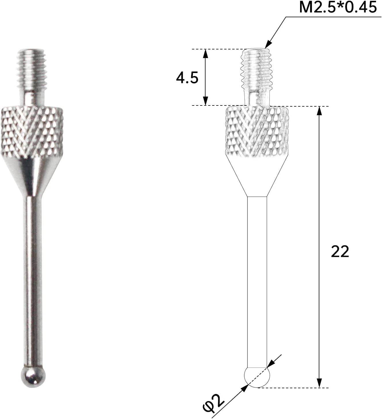
Figure 3: Probe Dimensions

Figure 4: Parts Reference List
5. Wiring Diagram
Connect the probe to your CNC control system according to the following diagram:

Figure 5: NPN-NO 3-Wire Wiring Diagram
- Red Wire (VCC): Connect to DC 5-24V power supply.
- Yellow Wire (IO/Signal Output): This is the signal output line. The high level is equivalent to VCC.
- Black Wire (GND/DCM): Connect to ground.
The indicator light will be green when power is supplied. It will turn red when the probe is triggered (contact is made).
6. Setup and Installation
6.1 Mounting the Probe
- Ensure your CNC machine is powered off before installation.
- Securely mount the 3D Touch Probe into an ER11 spring chuck. It is recommended to use chucks with AAA or higher accuracy (concentricity ≤0.005mm) to prevent deviations.
- Connect the probe's wiring to your CNC control board as per the wiring diagram in Section 5.
6.2 Adjusting Concentricity
After installation, it is crucial to adjust the probe's concentricity for accurate measurements. This process ensures the probe tip rotates perfectly centered.
Video 1: How to adjust concentricity and remove the probe tip. This video demonstrates the process of fine-tuning the probe's concentricity and how to safely disassemble and reassemble the probe tip.
- Position a lever gauge next to the probe tip. Note: Avoid using dial gauges with excessive elastic force, as this can affect accuracy.
- Manually rotate the probe tip for one full circle. Observe the lever gauge to identify the maximum and minimum values indicated by the pointer.
- Mentally divide the probe's circumference into four quadrants (A, B, C, D). Adjust the probe by gently tapping or applying pressure to the side that corresponds to the highest deviation. Begin by adjusting either the AC or BD axis first.
- Repeat the rotation and adjustment process until the concentricity is approximately 0.01mm.
- Once adjusted, move the spindle height so that the lower part of the probe tip ball head contacts the gauge ball head, and re-check the concentricity to confirm stability.
7. Operation
The 3D Touch Probe can be used for various measurement tasks on your CNC machine.
7.1 Centering of Round Holes
To find the center of a round hole:
- Mount the probe in the spindle.
- Carefully lower the probe into the round hole until the tip is below the top surface.
- Using your CNC software (e.g., Mach3, GRBL), initiate the centering routine. The probe will make contact with the inner walls of the hole at multiple points to calculate the precise center.
- The software will then set the workpiece origin or provide the offset values.

Figure 6: Probe in use for centering
7.2 Table Measurement
For measuring surfaces or setting Z-height:
- Position the probe above the surface to be measured.
- Initiate the surface probing routine in your CNC software. The probe will slowly descend until it makes contact with the surface.
- The software will record the Z-axis position upon contact, allowing for accurate tool length compensation or surface mapping.
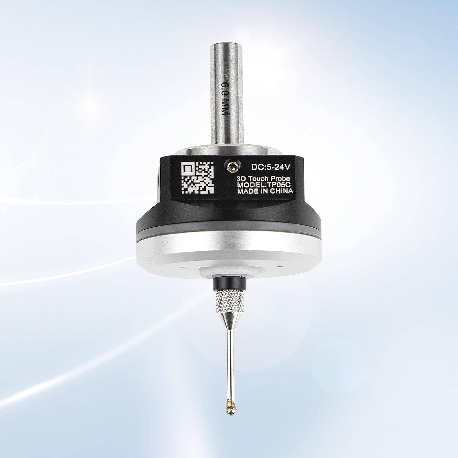
Figure 7: Probe measuring a surface
7.3 Supported Software
The probe is designed to work with common CNC control software:
- Mach3 (using Probe Wizard)
- GRBL (using GrblGru 1.1)

Figure 8: Compatible Software Interfaces
8. Maintenance
8.1 Stylus Tip Removal and Installation
The stylus tip can be replaced if damaged or for specific applications.

Figure 9: Probe with waterproof design
Figure 10: Stylus Tip Dimensions
- To remove the tip, insert the provided hex wrench into the probe removal hole.
- Gently press the tip into the measuring head and turn the wrench counter-clockwise to loosen and remove the tip.
- To install a new tip, align it with the measuring head, press down, and tighten clockwise with the wrench until secure.
8.2 General Care
- Keep the probe clean and free from debris, especially the stylus tip.
- Avoid applying excessive force to the probe tip, as this can damage the internal mechanism or affect accuracy.
- Store the probe in its protective case when not in use.
9. Troubleshooting
- Question: Is it necessary to turn on the spindle speed when using the probe?
Answer: No, never. The spindle should be stationary when using the probe. - Question: How do I distinguish the three wires?
Answer: The red wire is VCC (power), the black wire is GND (ground), and the yellow wire is IO (signal output). - Question: Why is the concentricity different every time the probe is installed?
Answer: This is often due to the ER chuck's uprightness. Many chucks may have inaccurate specifications. It is recommended to use high-precision ER chucks (AAA or above, concentricity ≤0.005mm). After installing the chuck, use a high-precision gauge or tungsten steel rod to check the concentricity on the table. For best results, place the dial indicator approximately 50mm from the chuck, which is roughly the distance between the probe's ball head and the tool handle's root.
10. Warranty and Support
For product support, technical assistance, or warranty inquiries, please contact the manufacturer, Changzhou Rattm Motor Co.,Ltd, or visit the official CNCTOPBAOS Store.