1. Introduction
This manual provides comprehensive instructions for the WWZMDiB RC522 RFID Reader Writer Module Kit. This kit is designed for use with microcontrollers such as Arduino, Raspberry Pi, and STM32, enabling contactless communication for various applications. It operates at a frequency of 13.56MHz and supports multiple Mifare card types.
2. Safety Information
- Ensure proper voltage (3.3V) is supplied to the module to prevent damage.
- Handle electronic components with care to avoid electrostatic discharge.
- Do not expose the module to moisture or extreme temperatures.
- Always disconnect power before making or changing connections.
3. Package Contents
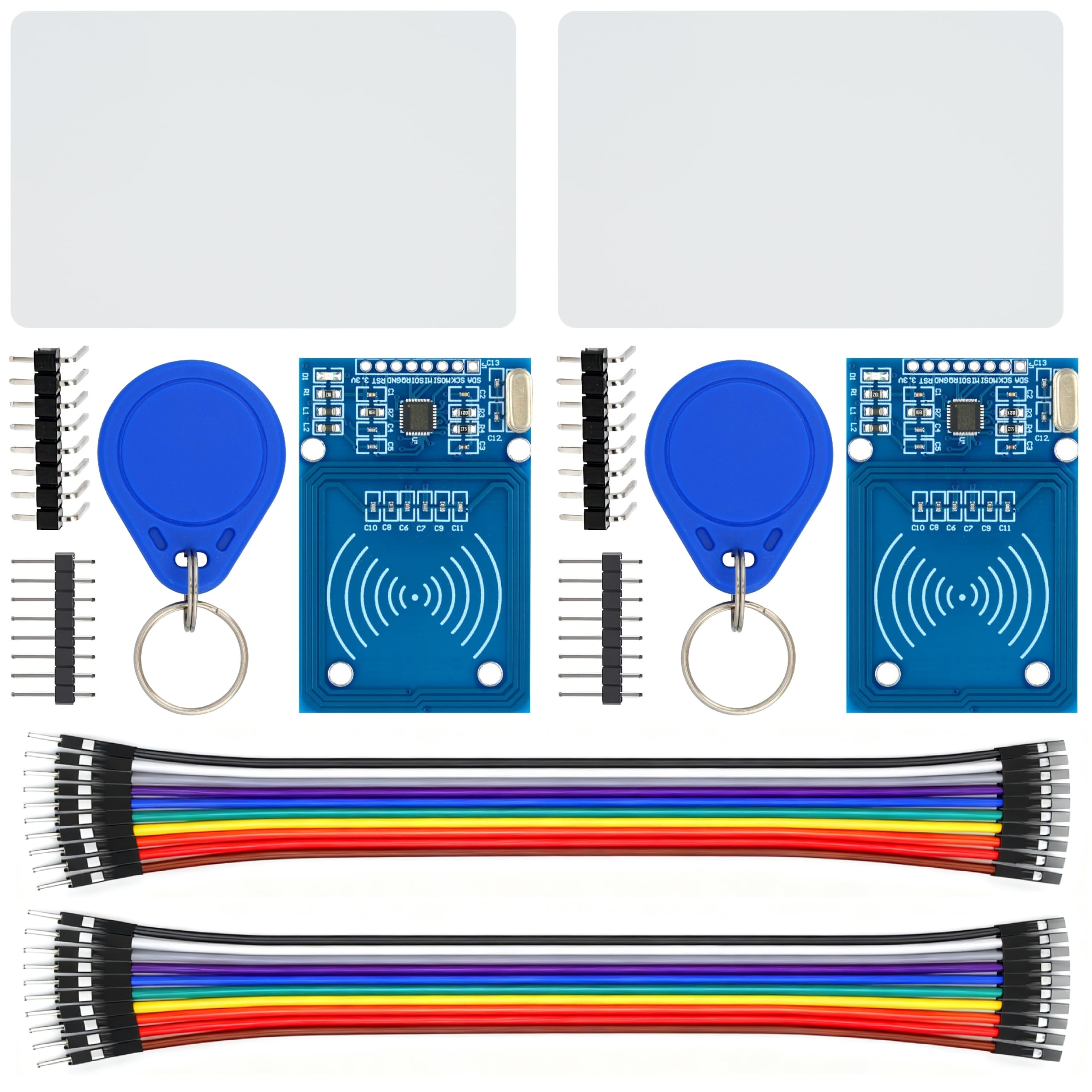
The WWZMDiB RC522 RFID Reader Writer Module Kit typically includes the following items:
- 2 x RC522 RFID Reader Writer Modules
- 2 x Standard S50 Blank Cards
- 2 x Key Fobs (Blue)
- 2 x Straight Pin Headers
- 2 x Bent Pin Headers
4. Product Overview
The RC522 module is a compact RFID reader/writer based on the MFRC522 chip. It is designed for easy integration into various embedded projects.
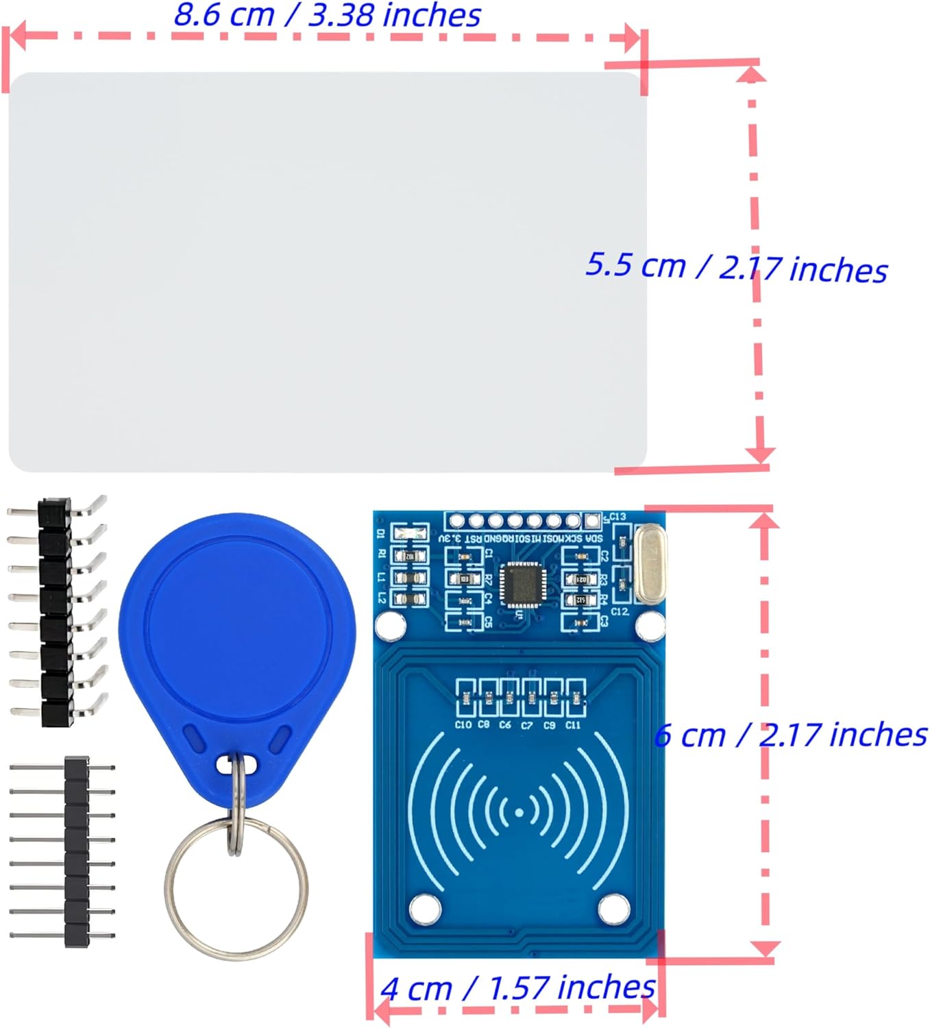
4.1. RC522 Module
The main component is the RC522 module, which handles the RFID communication. It features an integrated antenna and pin headers for connection to a microcontroller.


4.2. RFID Cards and Key Fobs
The kit includes blank S50 cards and key fobs, which are passive RFID tags compatible with the RC522 module. These can be programmed and read for various access control or identification projects.

5. Specifications
| Feature | Specification |
|---|---|
| Model | W-09-57-02 |
| Working Voltage | 3.3V |
| Working Frequency | 13.56MHz |
| Compatible Card Types | Mifare S50, Mifare S70, Mifare UltraLight, Mifare Pro, Mifare Desfire |
| Interface | SPI |
| Compatibility | Arduino, Raspberry Pi, STM32 |
| Item Weight | 2.08 ounces (approx. 59 grams for the kit) |
| Package Dimensions | 4.76 x 4.72 x 0.75 inches |
6. Setup
This section outlines the general steps for connecting the RC522 module to a microcontroller. Specific pinouts may vary slightly depending on your microcontroller board (Arduino, Raspberry Pi, STM32).
6.1. Pin Connections (SPI Interface)
The RC522 module communicates via the Serial Peripheral Interface (SPI). Connect the module to your microcontroller as follows:
- VCC (3.3V): Connect to the 3.3V power supply of your microcontroller.
- RST (Reset): Connect to a digital pin on your microcontroller.
- GND (Ground): Connect to the ground pin of your microcontroller.
- IRQ (Interrupt): Optional, connect to a digital pin for interrupt-driven operations.
- MISO (Master In Slave Out): Connect to the MISO pin of your microcontroller's SPI interface.
- MOSI (Master Out Slave In): Connect to the MOSI pin of your microcontroller's SPI interface.
- SCK (Serial Clock): Connect to the SCK pin of your microcontroller's SPI interface.
- SDA (Slave Select / Chip Select): Connect to a digital pin on your microcontroller. This pin selects the RC522 module for SPI communication.
6.2. Software Setup
To use the RC522 module, you will need to install a compatible library for your chosen microcontroller platform. For Arduino, the MFRC522 library by Miguel Balboa is commonly used. For Raspberry Pi, Python libraries are available.
- Install the appropriate library for your microcontroller IDE or environment.
- Refer to the library's documentation and examples for specific code implementation.
- Ensure your microcontroller's SPI interface is correctly configured.
7. Operating Instructions
Once the module is set up and the software is configured, you can begin reading and writing to RFID tags.
7.1. Reading RFID Tags
To read an RFID tag (card or key fob):
- Power on your microcontroller with the RC522 module connected.
- Run the reading sketch/program on your microcontroller.
- Place an RFID card or key fob near the RC522 module's antenna.
- The microcontroller will detect the tag and read its Unique ID (UID) and potentially other data stored on it. This data is typically displayed on a serial monitor or an attached display.
7.2. Writing to RFID Tags
To write data to a compatible RFID tag:
- Ensure you have a writable Mifare tag (like the S50 cards or key fobs provided).
- Load a writing sketch/program onto your microcontroller.
- Place the tag near the RC522 module.
- The program will attempt to write the specified data to the tag. Verify the write operation by reading the tag afterward.
Note: Writing to RFID tags requires understanding of Mifare Classic memory structure (sectors, blocks, keys). Refer to the MFRC522 library examples for detailed writing procedures.
Video 7.1: Demonstration of an RFID Kit, showing components and potential use cases. This video is provided by Stemedu, a seller.
8. Maintenance
The RC522 module is a robust electronic component, but proper care can extend its lifespan.
- Keep the module clean and free from dust and debris.
- Store in a dry, cool environment when not in use.
- Avoid bending or stressing the pin headers.
- Do not attempt to disassemble the module.
9. Troubleshooting
If you encounter issues with your RC522 module, consider the following troubleshooting steps:
- Module Not Detected:
- Check all wiring connections, especially VCC, GND, and SPI pins (MISO, MOSI, SCK, SDA).
- Ensure the module is receiving 3.3V power.
- Verify that the correct SPI pins are defined in your software.
- Confirm the library is correctly installed and initialized.
- Cannot Read Tags:
- Ensure the tag is a compatible Mifare type (S50, S70, UltraLight, Pro, Desfire).
- Place the tag very close to the module's antenna.
- Check for interference from other electronic devices.
- Verify that the reading code is correctly implemented.
- Cannot Write to Tags:
- Confirm the tag is writable and not read-only.
- Ensure correct authentication keys are used if the tag is protected.
- Verify the writing code logic and data format.
- Intermittent Operation:
- Check for loose connections or poor soldering.
- Ensure stable power supply.
- Consider adding a capacitor across VCC and GND near the module for power stability.
10. Warranty and Support
For warranty information or technical support, please refer to the seller's contact information provided at the point of purchase. Keep your purchase receipt as proof of purchase.
For additional resources and community support, you can often find extensive documentation, tutorials, and forums related to RC522 modules and their use with Arduino, Raspberry Pi, and STM32 online.