GMURA B0BDDW77RT
GMURA 150 Amp Dual Battery Isolator Kit User Manual
Model: B0BDDW77RT
1. Introduction
This manual provides comprehensive instructions for the installation, operation, and maintenance of your GMURA 150 Amp Dual Battery Isolator Kit. This intelligent voltage-sensitive relay is designed to manage dual battery systems in various vehicles, ensuring optimal charging and protection for both primary and auxiliary batteries.
2. Key Features
- Clever Design: High current 150 amps, universal voltage 12V/24V. Features an LED display for real-time voltage monitoring of both batteries and an emergency button to start the engine using the auxiliary battery if the primary battery is dead.
- Voltage Display: Displays 13.5V-16V for 12V systems and 27V-32V for 24V systems when connected. The isolator disconnects automatically when voltage drops below 12.5V. Note: There is a 5-second delay for automatic connection/disconnection.
- Applicable to Lithium Batteries: Includes a dedicated lithium battery connection cable to ensure stable performance in vehicles equipped with lithium batteries.
- Full Coverage: Ensures the main battery remains charged for vehicle starting, effectively providing two independent power sources with a single alternator.
- Wide Range of Applications: Compact design compatible with 12V/24V trucks, ATVs, UTVs, boats, RVs, vans, SUVs, campers, and other off-road vehicles.
3. Package Contents
Upon opening the package, verify that all components are present and undamaged:
- 1 x GMURA 150 Amp Dual Battery Isolator Unit
- 1 x Lithium Battery Connection Cable
- Mounting Hardware (screws, nuts, washers)
- Wire Terminals and Heat Shrink Tubing
- User Manual (this document)

Figure 3.1: Contents of the GMURA 150 Amp Dual Battery Isolator Kit, including the isolator unit, cables, and connectors.
4. Safety Information
WARNING: Improper installation can lead to serious injury, fire, or damage to your vehicle's electrical system. If you are not confident in your ability to install this device, seek professional assistance.
- Always disconnect the vehicle's main battery negative terminal before beginning any electrical work.
- Wear appropriate personal protective equipment, including safety glasses and gloves.
- Ensure all connections are secure and properly insulated to prevent short circuits.
- Do not exceed the maximum current rating of 150 Amps.
- Verify correct voltage (12V or 24V) compatibility with your vehicle's system.
- Keep the device away from flammable materials and excessive heat.
5. Setup and Installation
Follow these steps carefully for proper installation of the dual battery isolator.
5.1 Installation Overview
Video 5.1: A detailed guide on installing the 150 Amp Dual Battery Isolator Kit, demonstrating the connection process for main and auxiliary batteries.
5.2 Mounting the Isolator
- Choose a dry, secure location in your vehicle, away from engine heat and moving parts. Ensure adequate ventilation.
- Use the provided mounting hardware to securely fasten the isolator unit.

Figure 5.2: The GMURA 150 Amp Dual Battery Isolator, designed for compact installation in various vehicle types.
5.3 Wiring Connections
Refer to the diagram below and the video for detailed wiring instructions.
- Connect Main Battery Positive: Connect the positive terminal of your main (starting) battery to the "MAIN" positive terminal on the isolator.
- Connect Auxiliary Battery Positive: Connect the positive terminal of your auxiliary (house) battery to the "SUB" positive terminal on the isolator.
- Connect Negative Terminals: Connect the negative terminals of both the main and auxiliary batteries to a common ground point on the vehicle chassis, or directly to the negative terminal of the isolator if applicable (ensure proper grounding).
- Lithium Battery Connection (Optional): If using a lithium auxiliary battery, connect the provided lithium battery cable to the designated port on the isolator and to the accessory (ACC) side of the ignition switch. This helps maintain stable battery performance.
- Emergency Switch Wiring: The emergency switch allows manual linking of batteries. Connect the yellow wire to a switch, and the other end of the switch to a local ground. The blue wire can be connected to an indicator light to show when batteries are linked.
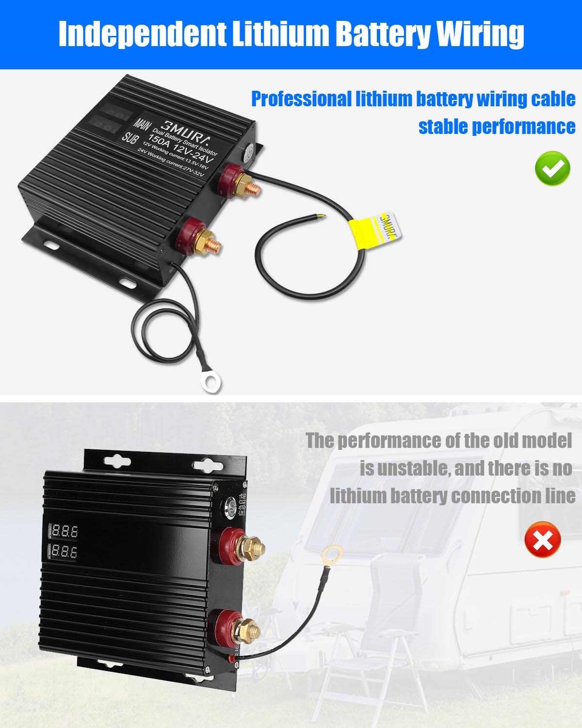
Figure 5.3: The dedicated lithium battery wiring ensures compatibility and stable performance for lithium auxiliary batteries.

Figure 5.4: The LED display provides real-time voltage readings for both the main and auxiliary batteries, allowing for easy monitoring.
6. Operating Instructions
The GMURA Dual Battery Isolator operates automatically, managing the charging of your auxiliary battery from the alternator once the main battery is sufficiently charged.
- Automatic Operation: When the engine is running and the main battery voltage reaches a sufficient level (typically above 13.5V for 12V systems), the isolator will automatically connect, allowing the auxiliary battery to charge.
- Automatic Disconnection: When the engine is off or the main battery voltage drops below a certain threshold (typically 12.5V), the isolator will automatically disconnect, preventing the auxiliary battery from draining the main battery.
- Emergency Start Function: In case your main battery is depleted and cannot start the engine, press the emergency button on the isolator. This will temporarily link the auxiliary battery to the main battery, providing power to start the engine. Release the button once the engine starts.
7. Maintenance
To ensure long-term performance and reliability of your GMURA Dual Battery Isolator, follow these maintenance guidelines:
- Regular Inspection: Periodically check all wiring connections for tightness and corrosion. Clean any corrosion with a wire brush and battery terminal cleaner.
- Cleanliness: Keep the isolator unit clean and free from dirt, dust, and moisture. Use a dry cloth for cleaning.
- Ventilation: Ensure the mounting location allows for adequate airflow around the unit to prevent overheating.
- Battery Health: Regularly check the health of both your main and auxiliary batteries. A faulty battery can affect the performance of the isolator.
8. Troubleshooting
| Problem | Possible Cause | Solution |
|---|---|---|
| Isolator not connecting/charging auxiliary battery. | Main battery voltage too low; faulty connections; faulty alternator. | Check main battery voltage (must be above 13.5V for 12V systems). Inspect all wiring connections. Test alternator output. |
| Auxiliary battery draining main battery. | Isolator not disconnecting; faulty isolator. | Ensure main battery voltage drops below 12.5V when engine is off. If issue persists, the isolator may be faulty and require replacement. |
| LED display not working. | No power to isolator; faulty display. | Check power connections to the isolator. If power is present, the display may be faulty. |
| Emergency start not working. | Faulty emergency switch wiring; auxiliary battery too low. | Check wiring to the emergency switch. Ensure auxiliary battery has sufficient charge. |
9. Specifications
- Brand: GMURA
- Model: B0BDDW77RT
- Current Rating: 150 Amps
- Operating Voltage: 12 Volts / 24 Volts (Universal)
- Operation Mode: Automatically
- Contact Type: Normally Open
- Connector Type: Auxiliary
- Terminal: Screw
- Circuit Type: 1-way
- Actuator Type: Ignition
- Contact Material: Copper
- Package Dimensions: 6.14 x 5.87 x 1.97 inches
- Weight: 1.23 Pounds
10. Warranty and Support
For warranty information and technical support, please refer to the product packaging or contact GMURA customer service directly. Keep your purchase receipt as proof of purchase.
Manufacturer: GMURA
First Available: September 7, 2022
For further assistance, please visit the official GMURA Store on Amazon.