
1. Introduction
This manual provides comprehensive instructions for the CENTURY AOKE DC 12V 2-Channel Wireless Remote Control Switch, Model ZK2DC. This device allows for wireless control of various DC 12V applications such as lights, motors, fans, alarm systems, and garage doors. It features stable signal transmission, high confidentiality, and low power consumption. Please read this manual carefully before installation and operation to ensure proper and safe use.
2. Product Overview
The product consists of a receiver module and two remote control transmitters. The receiver module (Model ZK2DC) is designed to receive 315MHz RF signals and control two independent relays. The transmitters (Model AK-J027) send control signals to the receiver.

Image 1: CENTURY AOKE DC 12V 2-Channel Wireless Remote Control Switch Receiver Module.
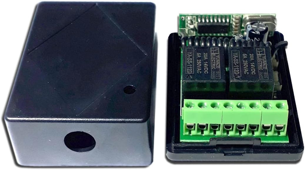
Image 2: The receiver module housed within its protective case.
3. Specifications
Receiver Module (Model: ZK2DC)
- Operating Voltage: DC 12V
- Quiescent Current: < 6mA
- Operating Temperature: -40°C to +80°C
- Receiver Sensitivity: > -105dBm
- Operating Frequency: 315MHz
- Output Voltage: DC and switch signal (optional)
- Maximum Load: 5A
- Dimensions: 4.5 cm x 3 cm x 1.5 cm
Transmitter (Model: AK-J027)
- Buttons: 2 buttons (A and B)
- Operating Frequency: 315MHz
- Remote Distance: 20-50 meters (open area)
- Operating Current: 13 mAh
- Encoding Type: EV1527 code
- Dimensions: 5.5 cm x 3 cm x 1.4 cm
- Battery: Included (CR2016 x 2)

Image 3: Receiver module dimensions (45mm x 30mm x 15mm).
4. Setup and Wiring
The transmitter and receiver are typically pre-paired from the factory. If re-pairing or changing operating modes is required, refer to Section 6. Learning and Clearing Remote Codes.
Receiver Pinout
The receiver board has screw terminals for power input and relay outputs. Refer to the image below for pin identification:

Image 4: Receiver board pinout. VCC (+) and GND (-) for power input. 1A, 1B, 1C for Relay 1 output (NC, COM, NO). 2A, 2B, 2C for Relay 2 output (NC, COM, NO).
- VCC: DC 12V Positive (+) power input
- GND: DC 12V Negative (-) power input
- Relay 1 Output:
- 1A: Normally Closed (NC) for Relay 1
- 1B: Common (COM) for Relay 1
- 1C: Normally Open (NO) for Relay 1
- Relay 2 Output:
- 2A: Normally Closed (NC) for Relay 2
- 2B: Common (COM) for Relay 2
- 2C: Normally Open (NO) for Relay 2
Wiring Diagrams
Below are example wiring diagrams for common applications. Ensure all connections are secure and correctly polarized.

Image 5: Top diagram shows wiring for two DC 12V lights. Bottom diagram shows wiring for a DC 12V motor, allowing for forward/reverse control using both relays.
Note: The maximum load for each relay is 5A. If your application requires more current, an external higher-rated relay or contactor must be used.
5. Operating Modes
The receiver supports three operating modes: Momentary, Latch, and Toggle. You can change the mode by pressing the learning button on the receiver board a specific number of times.

Image 6: Receiver board with key components labeled, including learning buttons and relays.
5.1. Momentary Mode (Jog Mode)
- To Set: Press the learning button on the receiver board 1 time.
- Operation: Press and hold a transmitter button (e.g., Button A) → Corresponding relay turns ON. Release the button → Relay turns OFF.
5.2. Latch Mode (Self-Locking Mode)
- To Set: Press the learning button on the receiver board 2 times.
- Operation: Press a transmitter button (e.g., Button A) → Corresponding relay turns ON. Press another transmitter button (e.g., Button B) → The first relay turns OFF. (This mode is typically used for interlocked control, where pressing one button turns on its relay and turns off any other active relay).
5.3. Toggle Mode (Interlock Mode)
- To Set: Press the learning button on the receiver board 3 times.
- Operation: Press a transmitter button (e.g., Button A) → Corresponding relay turns ON. Press the same button again → Relay turns OFF.
6. Learning and Clearing Remote Codes
This section details how to pair new transmitters or clear existing codes from the receiver.
6.1. Learning a Transmitter Button
- For Relay 1: Press the learning button 1 on the receiver board once. The LED indicator will flash. Then, press transmitter button A. The LED indicator will flash 5 times, indicating that button A has been successfully learned for Relay 1.
- For Relay 2: Press the learning button 2 on the receiver board once. The LED indicator will flash. Then, press transmitter button B. The LED indicator will flash 5 times, indicating that button B has been successfully learned for Relay 2.
6.2. Clearing All Remote Codes
- Press and hold the learning button on the receiver board for approximately 8 seconds.
- The LED indicator will turn OFF from ON.
- After releasing the button, press any button on your remote control. If the relay does not respond, it means all previously learned codes have been successfully cleared.
7. Troubleshooting
- Device not responding to remote:
- Check if the receiver is powered correctly (DC 12V).
- Ensure the transmitter batteries are not depleted. (The product description mentions one of the two remotes might have a dead battery upon arrival, requiring replacement of CR2016 x 2).
- Verify that the remote control is within the effective range (20-50 meters, line of sight). Obstacles like thick walls can reduce range.
- Re-learn the remote control code following the instructions in Section 6.1.
- Relay not switching correctly:
- Confirm the operating mode (Momentary, Latch, Toggle) is set as desired (Section 5).
- Check the wiring connections to the load (lights, motor) for correctness and security.
- Ensure the load current does not exceed the 5A maximum rating of the relay. Overloading can damage the relay or prevent proper operation.
- Interference issues:
- While designed for anti-interference, strong local RF signals might affect performance. Try relocating the receiver if possible.
8. Maintenance
- Keep the receiver module and transmitters clean and dry. Avoid exposure to moisture, extreme temperatures, or corrosive environments.
- Regularly check the transmitter batteries and replace them when performance degrades.
- Ensure all wiring connections remain tight and free from corrosion.
- Do not attempt to disassemble or repair the device yourself, as this may void any potential warranty and could lead to electric shock or damage.
9. Warranty and Support
This product is designed for reliability and performance. For any issues not covered in this manual, or for further assistance, please contact your retailer or the manufacturer directly. Please retain your proof of purchase for warranty claims. Specific warranty terms and conditions may vary by region and retailer.


