1. Introduction
This manual provides detailed instructions for the DWEII GY-NEO6MV2 NEO-6M GPS Module. It covers product features, specifications, setup procedures, operational guidelines, maintenance tips, and troubleshooting information. This module is designed for integration with various microcontrollers and flight control systems, including Arduino, MWC, and APM2.5.
2. Product Overview
The GY-NEO6MV2 NEO-6M GPS module is a compact and reliable solution for acquiring global positioning data. It features a NEO-6M GPS receiver, an integrated ceramic antenna for enhanced signal reception, and an EEPROM for saving configuration parameters. A data backup battery ensures settings are retained even without main power.
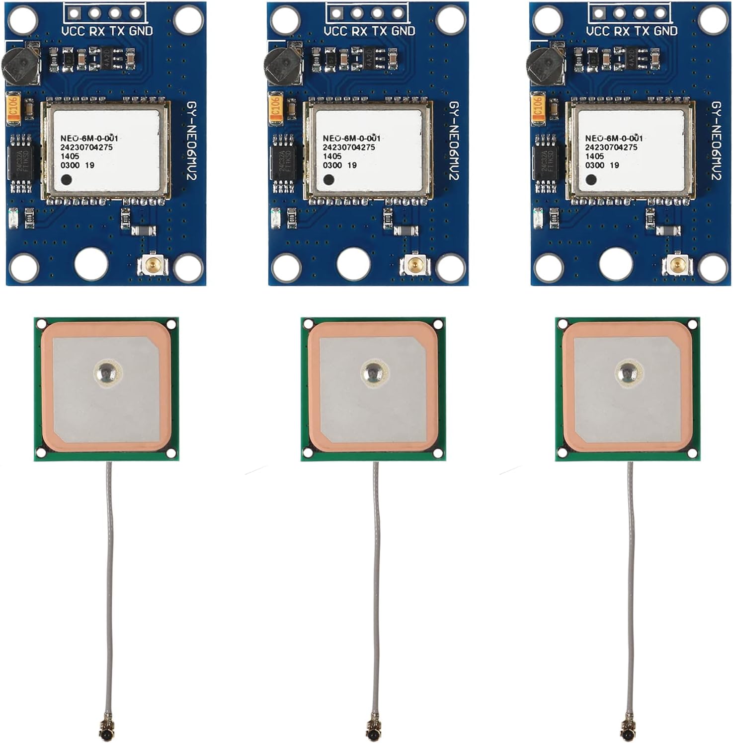
Image 2.1: Overview of three DWEII GY-NEO6MV2 GPS modules and their accompanying ceramic antennas.

Image 2.2: Detailed view of the GY-NEO6MV2 GPS module, highlighting the NEO-6M chip, pin connections (VCC, RX, TX, GND), and other onboard components.

Image 2.3: Detailed view of the ceramic GPS antenna, showing its square form factor and coaxial cable with a U.FL connector.
3. Specifications
| Feature | Description |
|---|---|
| Model | GY-NEO6MV2 |
| GPS Chipset | NEO-6M |
| Power Supply | 3V-5V DC |
| Antenna Type | Ceramic patch antenna (25x25mm) |
| Interface | RS232 TTL |
| Default Baud Rate | 9600 bps |
| Module Dimensions | 25mm x 35mm |
| Mounting Hole Diameter | 3mm |
| Special Features | EEPROM for configuration storage, data backup battery, LED signal indicator |
| Compatibility | Arduino, MWC, APM2.5, various flight control modules |
4. Setup
Follow these steps to set up your DWEII GY-NEO6MV2 NEO-6M GPS Module:
- Power Connection: Connect the VCC pin to a 3V-5V DC power supply and the GND pin to ground. Ensure the power supply is stable within this range.
- Data Connection: Connect the TX (Transmit) pin of the GPS module to the RX (Receive) pin of your microcontroller (e.g., Arduino) and the RX (Receive) pin of the GPS module to the TX (Transmit) pin of your microcontroller.
- Antenna Connection: Carefully connect the ceramic antenna's U.FL connector to the corresponding port on the GPS module. Ensure a secure connection. Position the antenna with a clear view of the sky for optimal signal reception.
- Baud Rate Configuration: The default baud rate for the module is 9600 bps. Configure your microcontroller's serial communication to match this baud rate for proper data exchange.
- Software Setup: If using with Arduino, libraries such as TinyGPS or TinyGPS++ are commonly used. Ensure your code initializes the serial port at 9600 baud.
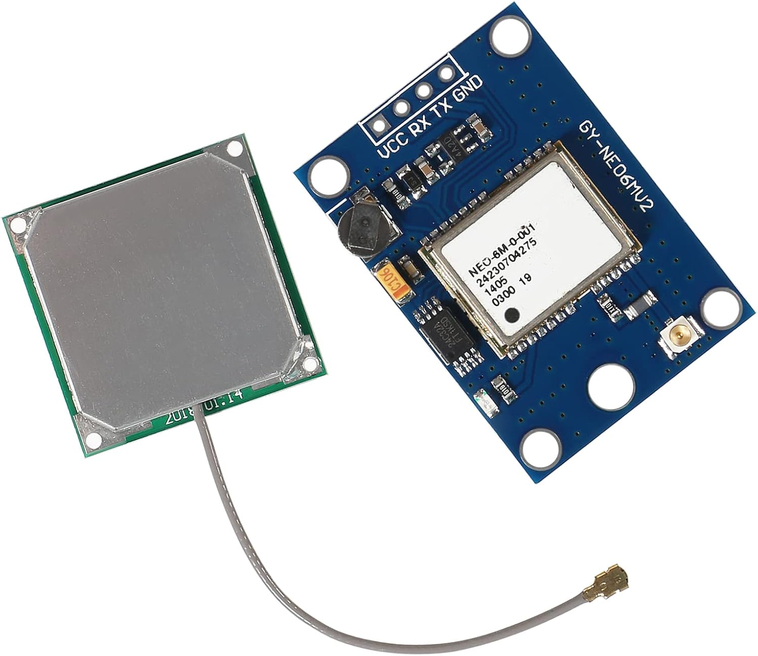
Image 4.1: Angled view of the GY-NEO6MV2 GPS module with the ceramic antenna connected via its coaxial cable.

Image 4.2: Top-down view of the GY-NEO6MV2 GPS module with the ceramic antenna connected, showing the compact assembly.
5. Operating Instructions
Once powered and connected, the GPS module will begin searching for satellite signals. The onboard LED signal indicator will provide feedback:
- No LED Activity: The module is powered but has not yet acquired a satellite fix.
- Blinking LED: The module has successfully acquired a satellite fix and is outputting GPS data.
The module outputs NMEA data sentences via its TTL serial interface. This data can be parsed by your microcontroller to extract latitude, longitude, altitude, time, and other navigational information. The EEPROM automatically saves configuration parameters, and the data backup battery helps maintain these settings during power cycles.
6. Maintenance
The DWEII GY-NEO6MV2 NEO-6M GPS Module requires minimal maintenance. Observe the following guidelines:
- Environmental Conditions: Operate the module within its specified temperature and humidity ranges. Avoid exposure to extreme temperatures, moisture, or corrosive environments.
- Physical Handling: Handle the module and antenna with care to prevent physical damage. Avoid bending or stressing the antenna cable and connector.
- Cleaning: If necessary, gently clean the module with a dry, soft cloth. Do not use liquids or abrasive cleaners.
- Firmware Updates: While not typically required for basic operation, consult the manufacturer's website or relevant community forums for any available firmware updates if advanced features or performance improvements are desired.
7. Troubleshooting
If you encounter issues with your GPS module, consider the following troubleshooting steps:
- No Satellite Fix (LED not blinking):
- Ensure the antenna has a clear, unobstructed view of the sky. Indoor operation or obstructions can prevent satellite acquisition.
- Verify the antenna is securely connected to the module.
- Allow sufficient time (up to several minutes) for the module to acquire a fix, especially during the first power-up or after a long period of inactivity.
- No Data Output / Incorrect Data:
- Check all power and data connections (VCC, GND, RX, TX) for proper wiring.
- Confirm that your microcontroller's serial port is configured to the correct baud rate (default 9600 bps).
- Ensure your software is correctly parsing the NMEA data. Test with a known working example sketch if possible.
- Module Gets Hot:
- Verify that the input voltage is within the specified 3V-5V range. Overvoltage can cause overheating and damage.
- Check for any short circuits in your wiring.
- Intermittent Signal:
- Relocate the antenna to an area with better sky visibility.
- Check for potential sources of electromagnetic interference near the module or antenna.
8. Warranty Information
This DWEII product is covered by a limited warranty. Please retain your proof of purchase for any warranty claims. For specific details regarding the warranty period and coverage, refer to the product packaging or contact your retailer.
9. Support
For further assistance or technical inquiries not covered in this manual, please refer to the following resources:
- Online Forums: Community forums for Arduino, flight control systems (MWC, APM), and general electronics often have extensive discussions and solutions related to GPS modules.
- Manufacturer's Website: Check the DWEII official website for additional documentation, drivers, or software tools.
- Retailer Support: Contact the retailer from whom you purchased the product for direct support or to initiate a warranty claim.