DORHEA SG90
SG90 Micro Servo Motor User Manual
Model: SG90
1. Introduction
This user manual provides essential information for the proper use, setup, operation, and maintenance of your DORHEA SG90 Micro Servo Motors. These compact and lightweight servos are designed for various applications, including RC helicopters, airplanes, cars, boats, and robotics projects. Please read this manual thoroughly before use to ensure optimal performance and longevity of your product.
2. Safety Information
- Ensure the power supply voltage is within the specified operating range (3.0V-6V) to prevent damage to the servo.
- Avoid applying excessive force or torque to the servo, as this can strip gears or damage the motor.
- Do not expose the servo to water or extreme temperatures outside the specified range (-30°C to +60°C).
- Keep out of reach of small children due to small parts.
- Always disconnect power before making any connections or disconnections.
3. Package Contents
Each package contains the following items:
- 8 x SG90 9G Micro Servo Motors
- Assorted servo horns (arms)
- Mounting screws

Figure 3.1: Contents of the SG90 Micro Servo Motor package, showing eight individual servo units along with their accompanying accessories like different types of servo horns and small screws for attachment.
4. Product Features
- Compact and lightweight design (9g).
- 180-degree rotation angle.
- Analog control system.
- Low power consumption.
- Compatible with various microcontrollers and RC systems.
- Includes multiple servo horns for diverse applications.
5. Specifications

Figure 5.1: Detailed product specifications for the SG90 servo motor.
| Parameter | Value |
|---|---|
| Control System | Change the pulse width |
| Amplifier Type | Analog controller |
| Operating Travel | 120°±10° (900→2100 μsec) |
| Rotation Angle | 180 degrees |
| Dead Band Width | 7 μsec |
| Neutral Position | 1500 μsec |
| Rotating Direction | Counter Clockwise (900→2100μsec) |
| Pulse Width Range | 900→2100 μsec |
| Operating Speed (no load, 4.8V) | 0.09±0.01 sec/60° |
| Operating Speed (no load, 6V) | 0.08±0.01 sec/60° |
| Running Current (no load, 4.8V) | 400±30mA |
| Running Current (no load, 6V) | 500±30mA |
| Stall Torque (locked, 4.8V) | 2.0±0.20kg·cm |
| Stall Torque (locked, 6V) | 2.2±0.20kg·cm |
| Stall Current (locked, 4.8V) | 1300±40mA |
| Stall Current (locked, 6V) | 1600±50mA |
| Idle Current (stopped, 4.8V) | 6±1mA |
| Idle Current (stopped, 6V) | 6±1mA |
| Running Life (no load, 4.8V) | >350000 Turns |
| Running Life (no load, 6V) | >320000 Turns |
| Operating Voltage | 3.0V~6V |
| Temperature Range | -30°C to +60°C |
| Weight | 9g |
| Package Dimensions | 7.2 x 5.12 x 1.02 inches |
| Item Weight | 6.4 ounces (total for 8 servos) |
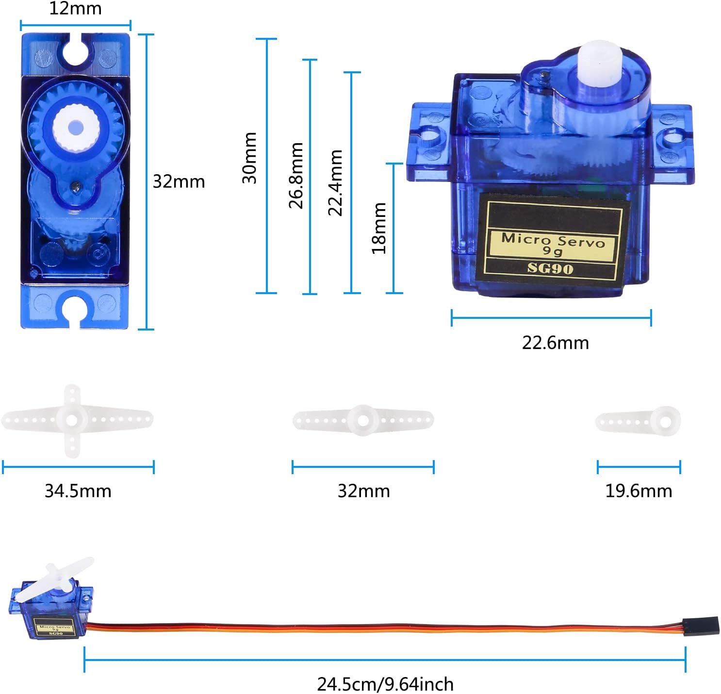
Figure 5.2: Physical dimensions of the SG90 servo and its accessories.
6. Setup
6.1 Wire Layout
The SG90 servo motor features a standard 3-wire interface for connection to your control board (e.g., Arduino, Raspberry Pi, RC receiver). The wires are color-coded for easy identification:
- Brown Wire: Ground (GND)
- Red Wire: Power (VCC, 3.0V-6V)
- Yellow Wire: Signal (PWM input)

Figure 6.1: SG90 Servo Wire Connections.
6.2 Connection Steps
- Connect the Brown wire of the servo to the Ground (GND) pin of your microcontroller or power supply.
- Connect the Red wire of the servo to the 5V (or appropriate VCC within 3.0V-6V) pin of your microcontroller or power supply. Ensure your power supply can provide sufficient current (starting current must be greater than 1A).
- Connect the Yellow wire of the servo to a digital pin capable of PWM output on your microcontroller (e.g., digital pin 9 on an Arduino).
- Securely mount the servo using the provided screws and appropriate servo horns for your application.
7. Operating
The SG90 is an analog servo that operates by receiving Pulse Width Modulation (PWM) signals. The width of the pulse determines the angular position of the servo arm.
7.1 Control Principle
- A pulse width of approximately 1500 μsec (1.5 ms) typically centers the servo arm.
- A pulse width of approximately 900 μsec (0.9 ms) moves the servo arm to one extreme (e.g., 0 degrees).
- A pulse width of approximately 2100 μsec (2.1 ms) moves the servo arm to the other extreme (e.g., 180 degrees).
- The servo requires a continuous PWM signal to maintain its position. If the signal stops, the servo may lose its holding torque.

Figure 7.1: SG90 Servo 180-Degree Control Angle.
7.2 Programming Example (Arduino)
For Arduino users, the built-in "Servo.h" library simplifies servo control. Here's a basic example to sweep the servo from 0 to 180 degrees:
#include <Servo.h>

Servo myServo;  // Create a servo object

void setup() {
  myServo.attach(9); // Attaches the servo on pin 9 to the servo object
}

void loop() {
  for (int pos = 0; pos <= 180; pos += 1) { // goes from 0 degrees to 180 degrees
    myServo.write(pos); // tell servo to go to position in variable 'pos'
    delay(15);          // waits 15ms for the servo to reach the position
  }
  for (int pos = 180; pos >= 0; pos -= 1) { // goes from 180 degrees to 0 degrees
    myServo.write(pos); // tell servo to go to position in variable 'pos'
    delay(15);          // waits 15ms for the servo to reach the position
  }
}
8. Maintenance
- Keep the servo clean and free from dust, dirt, and debris.
- Avoid exposing the servo to excessive moisture or corrosive substances.
- Regularly check the mounting screws to ensure they are tight and secure.
- Do not attempt to disassemble the servo unless you are an experienced technician, as this may void any potential warranty and can damage internal components.
- Ensure proper ventilation if operating in an enclosed space to prevent overheating.
9. Troubleshooting
| Problem | Possible Cause | Solution |
|---|---|---|
| Servo not moving or erratic movement | Incorrect wiring; Insufficient power supply; No or incorrect PWM signal; Damaged servo. |
|
| Servo "jitters" or vibrates | Noisy power supply; Weak signal; Mechanical binding; Servo overloaded. |
|
| Servo makes buzzing noise | Holding position under load; Insufficient power; Normal operation (slight buzz). |
|
| Servo gears stripped | Excessive force or sudden impact; Overload. |
|
10. Warranty and Support
For warranty information and technical support, please refer to the seller's policy on the platform where the product was purchased. You can also visit the official DORHEA store on Amazon for additional resources and contact information.
DORHEA Store: https://www.amazon.com/stores/Dorhea/page/F85A750B-FA04-45D7-9291-75A4C8F4D8C9
Ask a question about this manual
Ask about setup, troubleshooting, compatibility, parts, safety, or missing instructions. Manuals+ will review the question and use this page’s manual context to help answer it.