1. Introduction and Overview
The VIHELM GT5307B is a professional-grade insulation resistance tester designed for accurate measurement of insulation resistance, AC/DC voltage, and small resistance. This device is essential for electrical maintenance, testing, and troubleshooting in various industrial and scientific applications. It features a large LCD screen for clear readings, automatic discharge, and high voltage alarm for user safety.
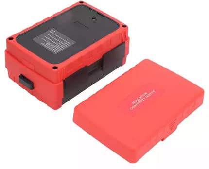
Image: Front view of the VIHELM GT5307B Insulation Resistance Tester, showcasing its robust red and black casing.
2. Key Features and Functions
The GT5307B offers a comprehensive set of features for reliable electrical testing:
- Measurement of insulation resistance
- AC measurement
- DC measurement
- Small resistance measurement
- Live detection of tested resistance
- Short circuit protection of measured resistance
- AC and DC automatic identification
- Measurement data lock (Data retention)
- Polarization Index (PI)
- Absorption Ratio Test (DAR)
- Automatic discharge function
- Low battery reminder
- Large LCD screen digital display
- External DC power supply DC9V 1.5A capability
- 10MΩ internal resistance measurement
- Over limit alarm
- Auto range selection
- Red alarm light and buzzer alarm for safety
- High voltage alarm
- Test voltage display
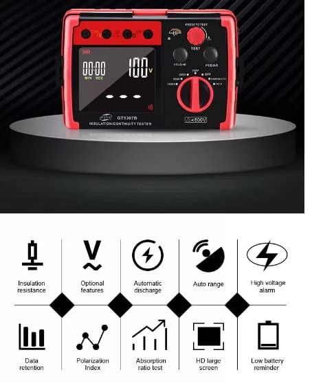
Image: Icons representing key features such as insulation resistance, optional features, automatic discharge, auto range, high voltage alarm, data retention, polarization index, absorption ratio test, HD large screen, and low battery reminder.
3. Parts Identification
Familiarize yourself with the components of the GT5307B Insulation Resistance Tester:
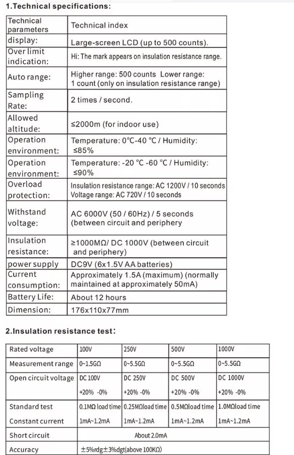
Image: Diagram illustrating the various parts of the GT5307B tester and its accessories.
- LINE hole (Input terminal for line connection)
- V hole (Voltage measurement input terminal)
- G hole (Guard terminal for insulation resistance measurement)
- EARTH hole (Ground terminal for insulation resistance measurement)
- HOLD / Sound switch button (To hold readings or toggle sound)
- TEST button (Initiates a test measurement)
- PI / DAR button (Activates Polarization Index or Dielectric Absorption Ratio tests)
- Rotary gear (Function selector switch)
- Technical parameters of DC port for external power (External power input)
- Black test lead with crocodile clip (Negative test lead)
- Red test lead with crocodile clip (Positive test lead)
4. Setup
4.1 Unpacking and Contents
Upon receiving your GT5307B, carefully unpack all components and verify that all items are present. The standard package includes:
- GT5307B Insulation Resistance Tester (x1)
- Test leads with crocodile clips (Red and Black)
- Carrying case
- User Manual
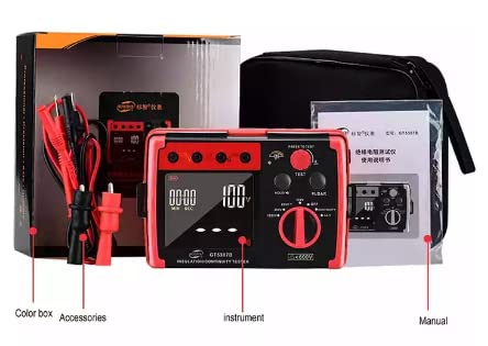
Image: The GT5307B tester, its color box packaging, accessories (test leads), carrying case, and user manual.
4.2 Battery Installation
The GT5307B is powered by 6x 1.5V AA batteries. To install or replace batteries:
- Locate the battery compartment on the rear of the device.
- Open the battery cover.
- Insert 6 AA batteries, ensuring correct polarity (+/-).
- Close the battery cover securely.
Alternatively, the device can be powered by an external DC9V 1.5A power supply via the dedicated DC port.
5. Operating Instructions
5.1 General Operation
Before any measurement, ensure the device is clean, the test leads are in good condition, and batteries are adequately charged. Always observe safety precautions when working with electrical systems.
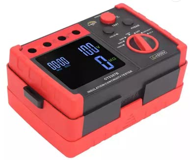
Image: Close-up view of the GT5307B's front panel, showing the LCD display, rotary switch, and control buttons.
5.2 Selecting Measurement Mode
Use the Rotary gear (8) to select the desired measurement function:
- OFF: Powers off the device.
- AC.V: For AC voltage measurement.
- DC.V: For DC voltage measurement.
- CONTINUITY: For continuity testing.
- 100V, 250V, 500V, 1000V: For insulation resistance measurement at specified test voltages.
5.3 Performing a Test
- Connect the test leads to the appropriate terminals (LINE, V, G, EARTH) and to the circuit under test.
- Select the desired measurement function using the Rotary gear.
- Press the TEST button (6) to initiate the measurement. The display will show the reading.
- For insulation resistance tests, hold the TEST button until the measurement is complete.
- To hold the current reading on the display, press the HOLD button (5). Press again to release.
5.4 PI/DAR Measurement
For Polarization Index (PI) or Dielectric Absorption Ratio (DAR) tests, select an insulation resistance voltage and then press the PI/DAR button (7). The device will automatically perform the timed measurements and calculate the ratio.
6. Specifications
6.1 Technical Parameters
| Technical parameters | Technical index |
|---|---|
| Display | Large-screen LCD (up to 500 counts) |
| Over limit indication | Hi: The mark appears on insulation resistance range. |
| Auto range | Higher range: 500 counts Lower range: 1 count (only on insulation resistance range) |
| Sampling Rate | 2 times / second. |
| Allowed altitude | ≤2000m (for indoor use) |
| Operation environment | Temperature: 0°C-40°C / Humidity: ≤85% |
| Storage environment | Temperature: -20°C-60°C / Humidity: ≤90% |
| Overload protection | Insulation resistance range: AC 1200V / 10 seconds Voltage range: AC 720V / 10 seconds |
| Withstand voltage | AC 6000V (50 / 60Hz) / 5 seconds (between circuit and periphery) |
| Insulation resistance | ≥1000MΩ/ DC 1000V (between circuit and periphery) |
| Power supply | DC9V (6x1.5V AA batteries) |
| Current consumption | Approximately 1.5A (maximum) (normally maintained at approximately 50mA) |
| Battery Life | About 12 hours |
| Dimension | 176x110x77mm |
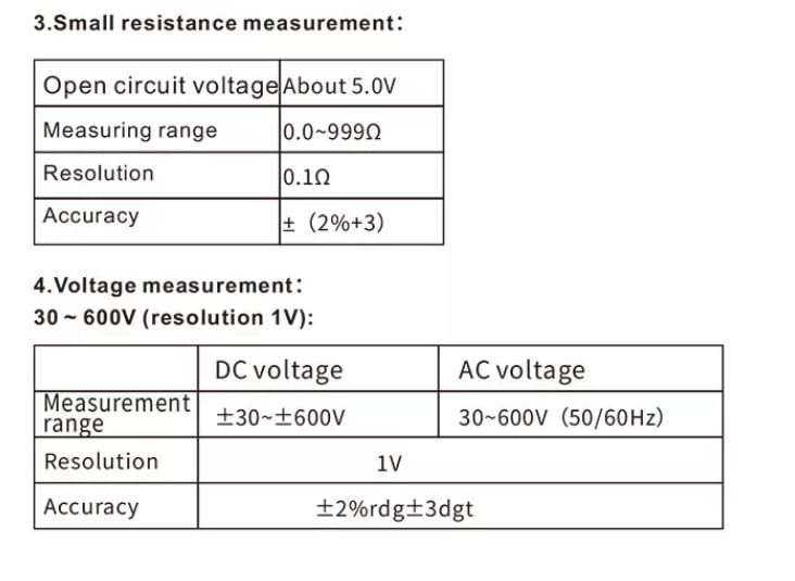
Image: Table detailing the technical parameters of the GT5307B Insulation Resistance Tester.
6.2 Insulation Resistance Test
| Rated voltage | 100V | 250V | 500V | 1000V |
|---|---|---|---|---|
| Measurement range | 0-1.5GΩ | 0-5.5GΩ | 0-5.5GΩ | 0-5.5GΩ |
| Open circuit voltage | DC 100V | DC 250V | DC 500V | DC 1000V |
| +20% -0% | +20% -0% | +20% -0% | +20% -0% | |
| Standard test | 0.1MΩ load time | 0.25MΩload time | 0.5MΩload time | 1.0MΩload time |
| Constant current | 1mA~1.2mA | 1mA~1.2mA | 1mA~1.2mA | 1mA~1.2mA |
| Short circuit | About 2.0mA | |||
| Accuracy | ±5%rdg±3dgt (above 100KΩ) | |||
6.3 Small Resistance Measurement
| Open circuit voltage | About 5.0V |
|---|---|
| Measuring range | 0.0~999Ω |
| Resolution | 0.1Ω |
| Accuracy | ± (2%+3) |
6.4 Voltage Measurement (30~600V, resolution 1V)
| Measurement range | DC voltage | AC voltage |
|---|---|---|
| ±30~±600V | 30~600V (50/60Hz) | |
| Resolution | 1V | |
| Accuracy | ±2%rdg±3dgt | |
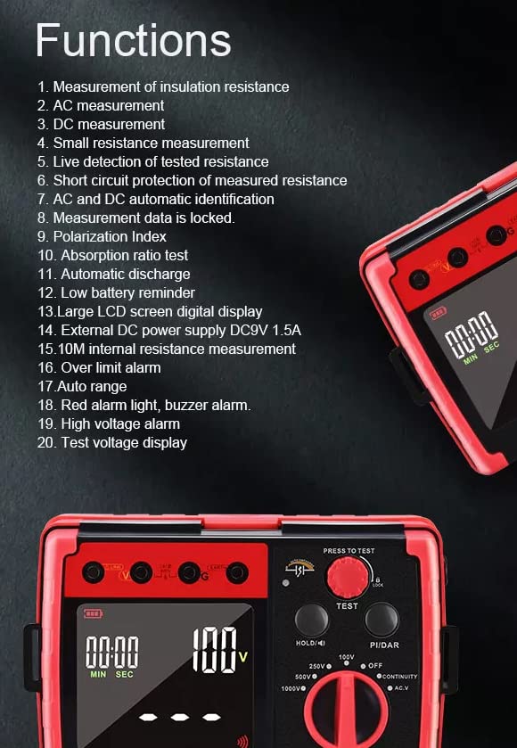
Image: Tables detailing the specifications for insulation resistance, small resistance, and voltage measurements.
7. Maintenance
Proper maintenance ensures the longevity and accuracy of your GT5307B Insulation Resistance Tester:
- Cleaning: Use a soft, dry cloth to clean the exterior of the device. Do not use abrasive cleaners or solvents.
- Storage: Store the device in a cool, dry place, away from direct sunlight and extreme temperatures. If storing for extended periods, remove the batteries to prevent leakage.
- Battery Replacement: Replace batteries promptly when the low battery indicator appears to ensure accurate measurements and prevent damage from depleted batteries.
- Test Leads: Regularly inspect test leads for any signs of damage, such as cracks in the insulation or exposed wires. Replace damaged leads immediately.
8. Troubleshooting
If you encounter issues with your GT5307B, consider the following common troubleshooting steps:
- Device not powering on: Check battery installation and ensure batteries are not depleted. Try replacing with new batteries or using an external power supply.
- Inaccurate readings: Ensure test leads are properly connected and not damaged. Verify the correct measurement mode is selected for the test. Check for external interference.
- Display issues: If the display is dim or flickering, replace batteries. If the issue persists, contact customer support.
- No response from buttons: Ensure the device is powered on. If still unresponsive, try removing and reinserting batteries.
For persistent issues or complex problems, please refer to the manufacturer's official support channels.
9. Warranty and Support
For information regarding product warranty, technical support, or service, please contact VIHELM customer service directly or refer to the warranty card included with your product. Keep your purchase receipt as proof of purchase for any warranty claims.