1. Introduction
This manual provides instructions for the Taidacent Wireless LED Inductive PCB Charger Pad. This device is designed to wirelessly power compatible LED lights through electromagnetic induction, offering a flexible and innovative lighting solution. Please read this manual thoroughly before use to ensure proper operation and safety.
2. Product Overview
2.1 Key Features
- Type C USB 5V power input.
- Capable of wirelessly charging more than 200 compatible LEDs simultaneously.
- Coil PCB size: 78mm diameter.
- Inductive distance: Up to 70mm.
- Designed for use with 4.3mm x 4.3mm LED sizes (Red, Golden, Orange, Green, Blue, Pink, White).
2.2 Package Contents
The package includes the Taidacent Wireless LED Inductive PCB Charger Pad (Model: 673b6a87-a502-40dd-a17b-70c6218cfc33).

Image: The Taidacent Wireless LED Inductive PCB Charger Pad, a circular black circuit board with a USB Type-C connector extending from one side.
3. Setup
- Power Connection: Connect the USB Type-C connector of the inductive PCB to a 5V USB power source (e.g., a wall adapter, power bank, or computer USB port). Ensure the power source can provide sufficient current for the number of LEDs you intend to use.
- Placement: Place the inductive PCB on a flat, stable surface.
- LED Positioning: Position compatible wireless LEDs within the inductive range (up to 70mm above the PCB). The LEDs will illuminate automatically when placed within the active field.
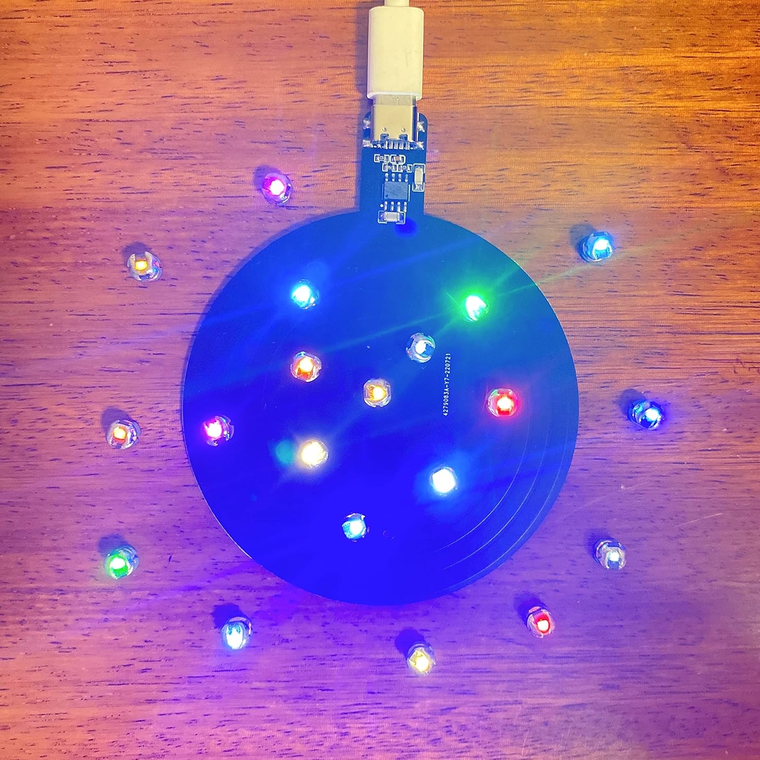
Image: The inductive PCB connected to a USB power source, with several small, colored LEDs glowing brightly around its surface, demonstrating wireless power transfer.
4. Operating Instructions
Once the inductive PCB is powered on, it continuously emits an electromagnetic field. Compatible wireless LEDs placed within this field will draw power and light up. No additional wiring or batteries are required for the LEDs themselves.
- Optimal Placement: For best brightness and performance, place LEDs directly above the PCB. The brightness may decrease as the distance from the PCB increases, up to the maximum inductive distance of 70mm.
- Multiple LEDs: The PCB can power over 200 LEDs simultaneously, provided they are within the inductive range and the power source is adequate.
- Orientation: The orientation of the LED lights can affect their brightness. Experiment with different orientations for optimal illumination.
Video: A demonstration of wireless LEDs lighting up when placed near an inductive coil, showcasing the product's functionality. The video highlights various colors of LEDs being powered without direct contact.

Image: The inductive PCB connected to a wall adapter, placed beneath a clear container filled with numerous small LEDs, which are all illuminated, demonstrating its use in a decorative setup.
5. Maintenance
- Cleaning: Use a soft, dry cloth to clean the surface of the PCB. Do not use liquid cleaners or abrasive materials.
- Storage: Store the device in a cool, dry place away from direct sunlight and extreme temperatures.
- Handling: Handle the PCB with care. Avoid bending or applying excessive force to the board or its components, especially the exposed chip and USB terminal.
6. Troubleshooting
| Problem | Possible Cause | Solution |
|---|---|---|
| LEDs do not light up. |
|
|
| LEDs are dim or flicker. |
|
|
| PCB is not functioning. |
|
|
7. Specifications
| Feature | Detail |
|---|---|
| Brand | Taidacent |
| Model Number | 673b6a87-a502-40dd-a17b-70c6218cfc33 |
| Connector Type | USB Type-C |
| Input Voltage | 5 Volts DC |
| Output Voltage | 5 Volts (Wireless Induction) |
| Coil PCB Size | 78mm diameter |
| Inductive Distance | Up to 70mm |
| Max LEDs Supported | More than 200 PCS |
| Compatible Devices | Wireless LED Lights |
| Material | Metal (PCB components) |
| Connectivity Technology | Type C, USB, Wireless |

Image: A diagram illustrating the dimensions of the inductive PCB, showing a 7.8cm diameter for the coil and a 7cm inductive height, with a Type C interface.
8. Warranty and Support
This product comes with a manufacturer's warranty as per standard terms. For specific warranty details or technical support, please refer to the seller's information or contact Taidacent directly. Keep your purchase receipt for warranty claims.
Warranty Description: Other (as per manufacturer's standard policy).