1. Introduction
This manual provides detailed instructions for the setup, operation, and maintenance of the innomaker CAM-MIPIOV7251 Global Shutter Camera. This camera module is designed for use with Raspberry Pi boards, offering a 0.3MP OV7251 sensor with global shutter technology, external trigger capabilities, and a frame rate of up to 158fps.

Image 1.1: innomaker CAM-MIPIOV7251 Global Shutter Camera module with attached ribbon cable.
2. Key Features
- Low-cost Raspberry Pi Global Shutter Camera module (CAM-MIPIOV7251RAW).
- Output formats: 8-bit RAW BW and 10-bit RAW BW.
- Resolution: 640x480 pixels with a frame rate of up to 158fps.
- Compatible with Raspberry Pi OS (dtoverlay ov7251) and includes Python demo.
- Provides innomaker driver source code and SDK for external trigger support.
- Supports 4 working modes for various application scenarios.

Image 2.1: Detailed specifications of the OmniVision OV7251 CCMOS Image Sensor, highlighting 640x480 resolution, Global Shutter, and 158fps frame rate.
3. Specifications
| Feature | Detail |
|---|---|
| Model Number | CAM-MIPIOV7251RAW |
| Sensor | OV7251 CCMOS Image Sensor |
| Resolution | 0.3 MP (640x480) |
| Shutter Type | Global Shutter |
| Frame Rate | Up to 158fps |
| Output Formats | 8-bit RAW BW, 10-bit RAW BW |
| External Trigger | Supported (Hardware and Software) |
| Lens Type | Wide Angle (D=148°, H=118°), Replaceable |
| Lens Holes | 20mm, 2xD2.0mm |
| Dimensions (LxWxH) | 1.26 x 1.26 x 1.26 inches (32 x 32 x 32 mm) |
| Item Weight | 1.76 ounces |
| Operating System Compatibility | Linux (Raspberry Pi OS) |
| Connectivity Technology | MIPI CSI-2 (via ribbon cable) |
| Photo Sensor Technology | CMOS |
| Maximum Focal Length | 0.01 Millimeters |
| Maximum Aperture | 2.8 f |

Image 3.1: Wide angle lens specifications, showing a diagonal field of view of 148° and horizontal of 118°.

Image 3.2: Camera module dimensions (32mm x 32mm) and illustration of the replaceable lens feature.
4. Package Contents
The innomaker CAM-MIPIOV7251 package typically includes:
- innomaker CAM-MIPIOV7251 Camera Module
- Driver Source Code (available for download)
- Flexible Flat Cable (FFC) for Raspberry Pi connection
5. Setup Instructions
5.1. Hardware Connection
- Ensure your Raspberry Pi is powered off and disconnected from the power supply.
- Locate the CSI (Camera Serial Interface) port on your Raspberry Pi board. This is typically a long, narrow connector.
- Gently pull up the plastic clip on the CSI connector.
- Insert the flexible flat cable (FFC) from the camera module into the CSI port, ensuring the silver contacts on the cable face the silver contacts in the connector. The blue tab on the cable should face away from the Ethernet port on most Raspberry Pi models.
- Push the plastic clip back down to secure the cable.
- Connect the other end of the FFC to the camera module's connector in the same manner.
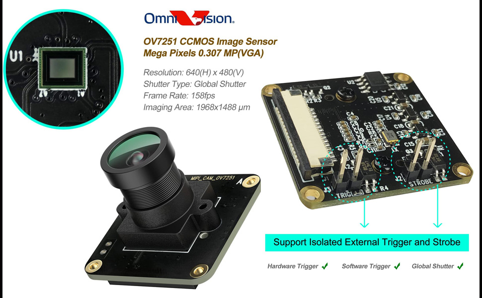
Image 5.1: The innomaker CAM-MIPIOV7251 camera module connected to a Raspberry Pi board via its flexible flat cable, illustrating compatibility with various Pi models.
5.2. Software Configuration
The innomaker CAM-MIPIOV7251 requires specific drivers and configuration on your Raspberry Pi OS. Refer to the official innomaker GitHub repository for the latest driver source code, SDK, and Python demos.
- Driver Installation: Download and compile the provided driver source code. Instructions are typically found in the repository's README file.
- dtoverlay Configuration: Enable the OV7251 camera module using the Raspberry Pi's
dtoverlaymechanism. This usually involves editing/boot/config.txt. - Python Demos: Utilize the provided Python demo scripts to test camera functionality and capture images/video.
Important: For detailed and up-to-date instructions, always consult the official GitHub repository:
https://github.com/INNO-MAKER/cam-mipiov7251-trigger

Image 5.2: Screenshot showing the innomaker GitHub repository, which contains driver source code, SDK, and user manuals for the CAM-MIPIOV7251.
6. Operating Instructions
6.1. Basic Image Capture
Once the drivers are installed and the camera is recognized by your Raspberry Pi, you can use the provided Python demos or standard camera tools (if compatible) to capture images and video. The global shutter ensures that fast-moving objects are captured without distortion.
6.2. External Trigger and Strobe
The CAM-MIPIOV7251 supports isolated external hardware and software triggers, as well as strobe functionality. These features are crucial for applications requiring precise synchronization, such as machine vision or high-speed event capture.
- Hardware Trigger: Connect external trigger signals to the designated pins on the camera module (labeled J1, J2, J3, STROBE). Refer to the SDK documentation for pin assignments and signal requirements.
- Software Trigger: Utilize the provided SDK to implement software-based triggering, allowing your Raspberry Pi application to initiate image capture programmatically.

Image 6.1: Close-up view of the camera module highlighting the pins for isolated external trigger (J1, J2, J3) and strobe functionality.
6.3. Working Modes
The innomaker driver supports four distinct working modes to fulfill different application scenarios. Details on configuring and utilizing these modes are available in the driver documentation and SDK.
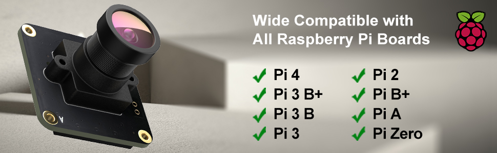
Image 6.2: Diagram illustrating the four working modes supported by the innomaker camera driver, designed for various application needs.
7. Maintenance
- Cleaning: Use a soft, lint-free cloth to gently clean the lens. For stubborn smudges, a specialized lens cleaning solution can be applied to the cloth (not directly to the lens).
- Handling: Avoid touching the sensor or the flexible flat cable contacts directly. Handle the camera module by its edges.
- Storage: Store the camera in a dry, dust-free environment when not in use.
- Lens Replacement: The lens is replaceable. If you need to change the lens, ensure the replacement lens is compatible and follow proper optical handling procedures to avoid dust or damage to the sensor.
8. Troubleshooting
8.1. Camera Not Detected
- Check Connections: Ensure the flexible flat cable is securely seated in both the Raspberry Pi's CSI port and the camera module's connector. Verify the cable orientation (silver contacts facing each other).
- Power Cycle: Restart your Raspberry Pi after checking connections.
- Driver Installation: Confirm that the correct innomaker drivers are installed and configured according to the GitHub instructions. Verify
dtoverlaysettings in/boot/config.txt. - Compatibility: Ensure your Raspberry Pi model is compatible (Pi 5, 4B, 3B+, 3B, 3A+, CM3+, CM3, Pi Zero W are supported).
8.2. Image Quality Issues
- Lens Cleanliness: Clean the camera lens as described in the Maintenance section.
- Lighting Conditions: Ensure adequate and appropriate lighting for your application.
- Software Settings: Adjust camera parameters (exposure, gain, white balance) through the software interface or SDK.
8.3. External Trigger Not Functioning
- Wiring: Double-check the wiring of your external trigger signals to the camera module's pins.
- Signal Levels: Verify that the external trigger signals meet the voltage and timing requirements specified in the SDK documentation.
- Software Implementation: Ensure your software is correctly configured to listen for and respond to external trigger events.
9. Support and Warranty
For technical support, driver updates, and additional resources, please visit the official innomaker GitHub repository or their official website.
Warranty information for the innomaker CAM-MIPIOV7251 is typically provided at the point of purchase or on the manufacturer's official website. Please retain your proof of purchase for warranty claims.


