
1. Product Introduction
The Teyleten Robot CH32V307VCT6 Development Board features a Highland barley V4F processor, operating at up to 144MHz system frequency. It supports single-cycle multiplication and hardware division, along with a hardware floating point operation unit (FPU). The board includes 64KB SRAM and 256KB Flash memory.
Key features include:
- Power supply voltage: 2.5/3.3V
- GPIO unit independent power supply
- Multiple low power modes: sleep, stop, standby
- Power-on/power-off reset, programmable voltage detector
- 2 groups of 18 general-purpose DMA channels
- 4 groups of operational amplifiers (op amps) comparators
- 1 random number generator (TRNG)
- 2 groups of 12-bit DAC conversion
- 2-unit 16-channel 12-bit ADC conversion, 16-channel touch key (TouchKey10 timer)
- USB2.0 full speed OTG interface
- USB2.0 high-speed host/device interface (480Mbps built-in PHY) with 3 USART interfaces and 5 UART interfaces
- 2 CAN interfaces (2.0B active)
- SDIO interface, FSMC interface, DVP digital image interface
- 2 groups of IIC interfaces, 3 groups of SPI interfaces, 2 groups of I2S interfaces
- Gigabit Ethernet Controller (ETH) with built-in 10M PHY
- 80 I/O ports, which can be mapped to 16 external interrupts
- CRC calculation unit, 96-bit chip unique ID
- Serial 2-wire debug interface

Image 1.1: The CH32V307VCT6 Development Board, showcasing its compact design and integrated Ethernet port.
2. Functional Diagram and Pinout
This section provides an overview of the board's key components and their locations, aiding in proper connection and usage.

Image 2.1: Functional diagram highlighting various components and their functions.
- TF SD holder: For external storage.
- Serial 2-wire debug port: Similar to ARM's SWD port for debugging.
- Type-C USB 2.0 (B6/B7): Can be used to download programs.
- Power Indicator: LED indicating power status.
- EEPROM 24C32 (or 64): Electrically Erasable Programmable Read-Only Memory.
- SPIFlash W25Q16 (or 32): Serial Peripheral Interface Flash memory.
- LDO 1A: Low Dropout 1A voltage regulator.
- Resettable fuse: Provides overcurrent protection.
- Type-C USB 2.0 (A11/A12): Can be used to download programs.
- Isolated network port: For Ethernet connectivity.
- LED1:A15, LED2:B4: User-programmable LEDs.
- CH32V307VCT6: The main microcontroller unit.
3. Schematic Diagram
The complete circuit schematic provides detailed information on component connections and electrical pathways. This is essential for advanced users for troubleshooting, custom modifications, or deeper understanding of the board's design.
A detailed schematic diagram is available for reference in the product documentation.
4. Setup and Operation
4.1 Onboard LEDs and Buttons
The development board includes several onboard indicators and control buttons:
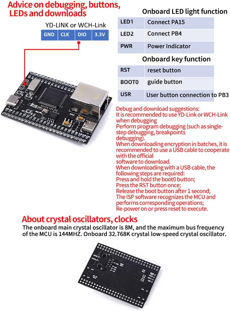
Image 4.1: Overview of onboard LEDs, buttons, and debugging interface.
| LED | Function |
|---|---|
| LED1 | Connects to PA15 |
| LED2 | Connects to PB4 |
| PWR | Power indicator |
| Button | Function |
|---|---|
| RST | Reset button |
| BOOT0 | Guide button (for boot mode selection) |
| USR | User button connection to PB3 |
4.2 Crystal Oscillators and Clocks
The onboard main crystal oscillator operates at 8MHz, and the maximum bus frequency of the MCU is 144MHz. An onboard 32.768K crystal low-speed crystal oscillator is also included for real-time clock functions.
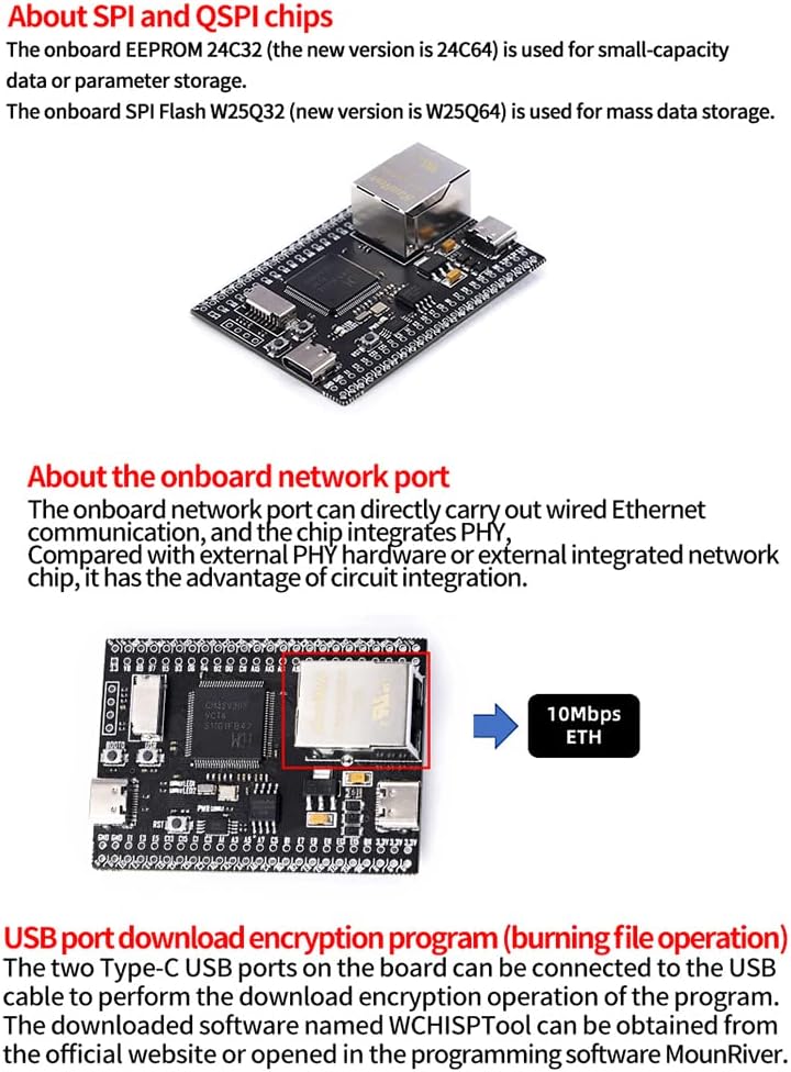
Image 4.2: Underside view of the development board, indicating the location of crystal oscillators.
5. Memory Chips
5.1 SPI and QSPI Flash
The onboard EEPROM 24C32 (newer versions may use 24C64) is utilized for small-capacity data storage or parameter configuration. For mass data storage, the onboard SPI Flash W25Q32 (newer versions may use W25Q64) is provided.
Image 5.1: Location of EEPROM and SPI Flash memory chips on the board.
6. Network Connectivity
6.1 Onboard Network Port
The development board features an onboard network port that supports wired Ethernet communication. It integrates a Physical Layer (PHY) chip, offering a compact and integrated solution compared to external PHY hardware.

Image 6.1: The onboard network port, capable of 10Mbps Ethernet communication.
7. Programming and Debugging
7.1 USB Program Download and Encryption
To download programs to the CH32V307VCT6 board, follow these steps:
- Connect the board to your computer using a Type-C USB cable.
- Open the WCHISPTool software and configure the corresponding options, such as whether the downloaded file is encrypted or not.
- Press and hold the BOOT0 button, then press the RST button once.
- Release the RST button after approximately 1 second, and then release the BOOT0 button.
- The software should automatically identify the device that needs to be downloaded.
- Click 'Download' to complete the program download and encryption process.

Image 7.1: WCHISPTool interface for downloading and encrypting programs via USB.
7.2 Development Environment
Since the MCU core is RISC-V, traditional ARM-based IDEs like Keil-MDK are not directly compatible. The recommended development environment is MounRiver Studio (MRS), which supports both Windows and Linux operating systems. MRS provides comprehensive support for RISC-V development, including RT-Thread, FreeRTOS, OpenOCD, and GCC toolchains.
A visual representation of the MounRiver Studio development environment.
7.3 Debugger Compatibility
Due to the RISC-V core, standard ARM microcontroller debuggers are not compatible. Dedicated debuggers such as YD-Link or WCH-Link are recommended for debugging. The DAP-CMSIS debugger can be used for ARM single-chip microcontrollers, but for the CH32V series, a dedicated debugger is required. MounRiver Studio supports single-step debugging and breakpoint functionality.
An example of a compatible debugger cable for the development board.
8. Specifications
| Feature | Detail |
|---|---|
| Brand | Teyleten Robot |
| Processor Core | RISC-V V4F |
| System Frequency | Up to 144MHz |
| Flash Memory | 256 KB |
| SRAM | 64 KB |
| Connectivity Technology | Ethernet, I2C, USB |
| Wireless Communication Standard | Bluetooth (Wireless Compability) |
| Processor Count | 1 |
| Manufacturer | Teyleten Robot |
| ASIN | B0B7TJ5F7V |
9. Troubleshooting
This section provides general guidance for common issues. For specific problems, refer to the official Teyleten Robot support resources or community forums.
- Board not powering on: Ensure the USB cable is securely connected to a power source and the board. Check for any visible damage or short circuits.
- Program download failure: Verify that the correct COM port is selected in WCHISPTool. Ensure BOOT0 and RST buttons are pressed and released in the correct sequence as described in Section 7.1. Check USB cable integrity.
- Debugger not connecting: Confirm that you are using a RISC-V compatible debugger (e.g., YD-Link, WCH-Link). Ensure drivers are correctly installed and the debugger is properly connected to the board's debug port.
- IDE not recognizing board: Make sure MounRiver Studio is correctly installed and configured. Check USB connections and ensure the board is in the correct boot mode for programming/debugging.
10. Maintenance
To ensure the longevity and proper functioning of your development board, follow these maintenance guidelines:
- Storage: Store the board in a dry, anti-static environment, away from direct sunlight and extreme temperatures.
- Cleaning: Use a soft, dry brush or compressed air to remove dust. Avoid using liquids or abrasive cleaners.
- Handling: Always handle the board by its edges to avoid touching components, especially when powered. Use anti-static precautions (e.g., anti-static wrist strap) to prevent electrostatic discharge (ESD) damage.
- Power Supply: Use a stable and appropriate power supply (2.5V/3.3V) to prevent damage to the board.
11. Warranty and Support
For warranty information, technical support, and additional resources, please visit the official Teyleten Robot website or contact their customer service. Keep your purchase receipt for warranty claims.
Official Teyleten Robot Store: Teyleten Robot Amazon Store