1. Introduction
This manual provides essential information for the safe and efficient operation, setup, and maintenance of your VECTOR WELDING DC TIG 200A IGBT Combi Welding Machine. Please read this manual thoroughly before using the equipment and keep it for future reference.
The DC TIG welding machine includes a TIG torch package with a ground clamp and electrode holder, suitable for welding electrodes. It can be used to weld various metals such as steel, stainless steel, titanium, magnesium, and copper. The TIG welding process offers a powerful 200 A output. For electrode (MMA) welding, the machine provides 170 A. Supporting functions like Hotstart, Anti-stick, and Arc-Force are integrated for enhanced performance. This combi welding machine features high-frequency (HF) ignition for TIG welding and supports both 2-stroke and 4-stroke control modes for the TIG torch.
2. Safety Information
WARNING: Welding can be dangerous. Always follow safety precautions to prevent injury or death.
- Always wear appropriate personal protective equipment (PPE), including a welding helmet with proper shade, flame-resistant clothing, welding gloves, and safety shoes.
- Ensure adequate ventilation to avoid inhaling welding fumes.
- Protect bystanders from arc rays and hot metal.
- Never weld near flammable materials.
- Ensure the welding machine is properly grounded.
- Disconnect power before performing any maintenance or changing accessories.
- Do not touch live electrical parts.
3. Package Contents
Verify that all items are present in the package:
- DC Combi Welding Machine (TIG 200A)
- TIG Torch (WP26 type)
- Nozzle Starter Kit for TIG Torch
- Ground Clamp with Cable
- Electrode Holder with Cable
- Gas Connection Hose
- User Manual
4. Product Overview
4.1. Welding Machine Components

4.2. Accessories


5. Setup
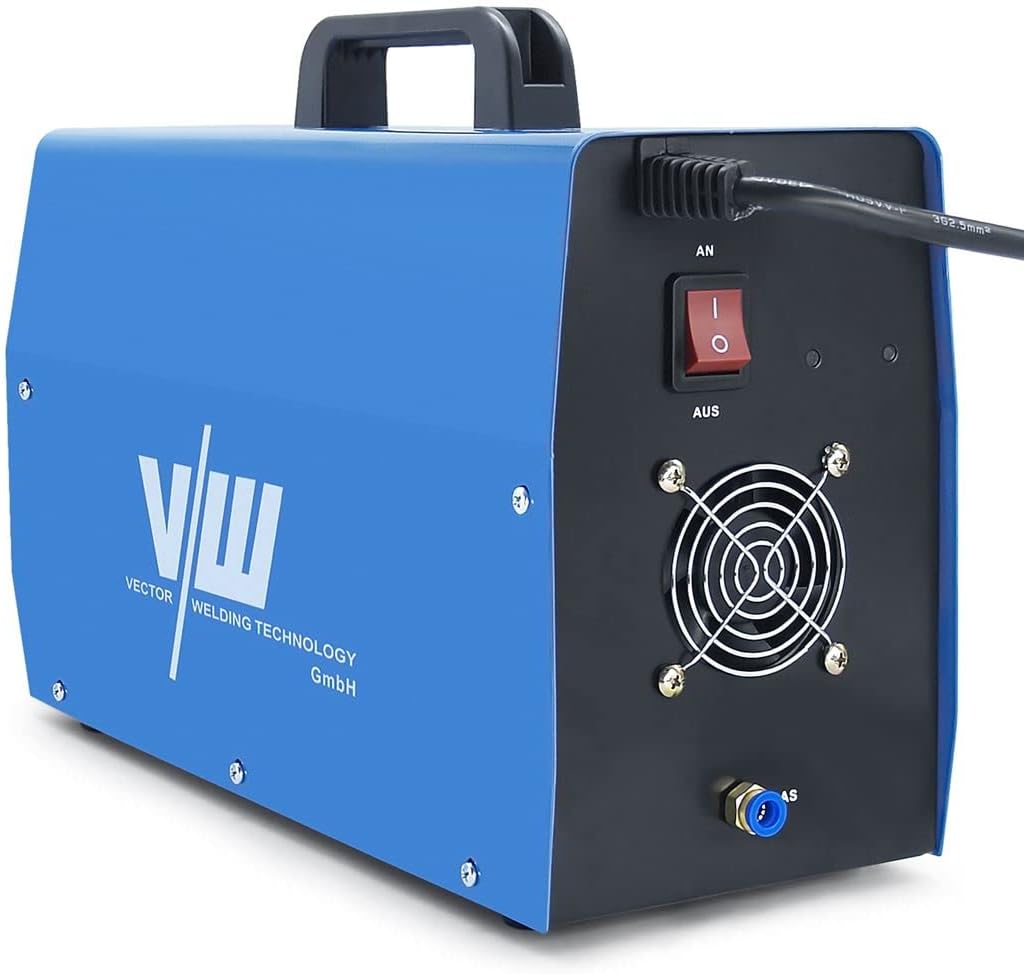
5.1. Power Connection
- Ensure the welding machine's power switch (located on the rear panel) is in the 'OFF' position.
- Connect the power cable to a suitable power outlet (AC 230V). Ensure the power supply meets the machine's requirements.
5.2. Gas Connection (for TIG Welding)
- Connect one end of the gas connection hose to the gas inlet on the rear panel of the welding machine.
- Connect the other end of the gas hose to your inert gas cylinder (e.g., Argon) via a pressure regulator.
- Ensure all connections are tight to prevent gas leaks.
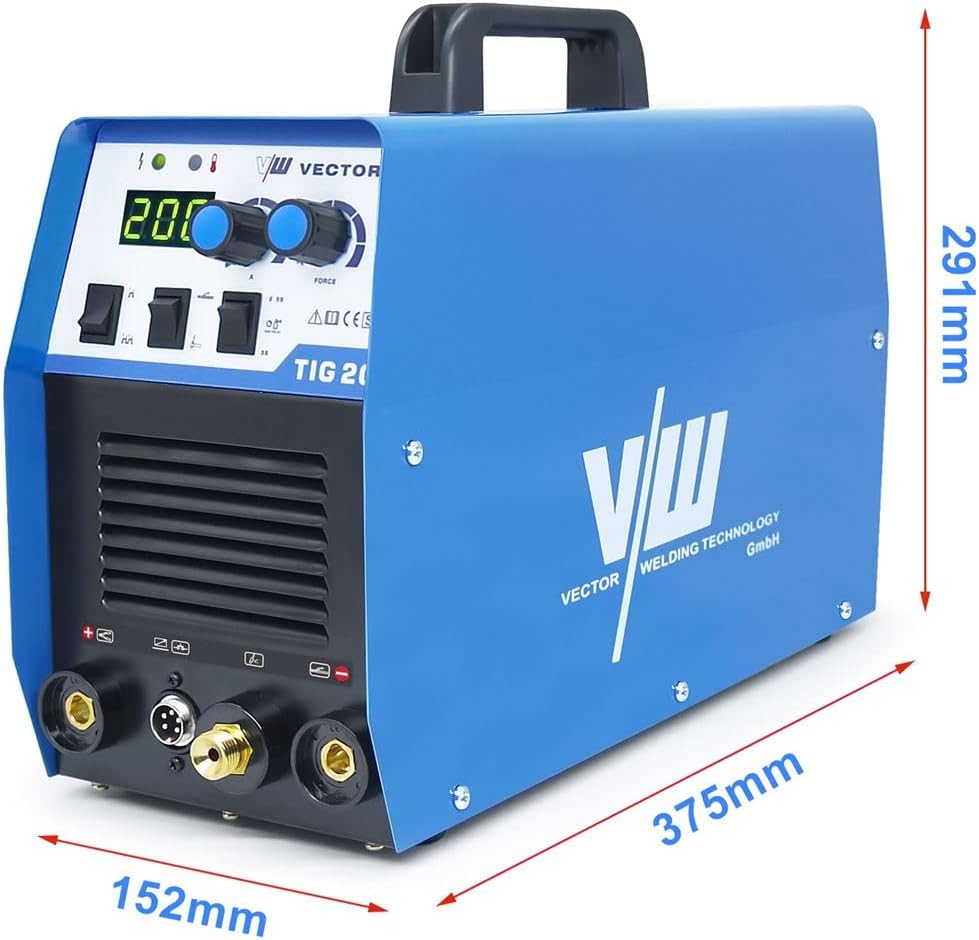
5.3. TIG Torch Connection
- Insert the power cable connector of the TIG torch into the designated TIG torch port on the front panel (usually marked with a negative (-) symbol or 'TIG').
- Secure the connection by twisting the connector clockwise.
- Connect the control cable of the TIG torch to the multi-pin connector on the front panel.
- Connect the gas hose from the TIG torch to the gas outlet on the front panel.
5.4. Ground Clamp Connection
- Connect the ground clamp cable to the positive (+) terminal on the front panel for DC TIG welding.
- Attach the ground clamp securely to the workpiece or welding table, ensuring good electrical contact.
5.5. Electrode Holder Connection (for MMA Welding)
Note: This step is only for MMA (Stick) welding.
- Connect the electrode holder cable to the positive (+) terminal on the front panel.
- Connect the ground clamp cable to the negative (-) terminal on the front panel.
6. Operating Instructions
6.1. Powering On/Off
- To power on, flip the main power switch on the rear panel to the 'ON' position. The digital display will illuminate.
- To power off, flip the main power switch to the 'OFF' position.
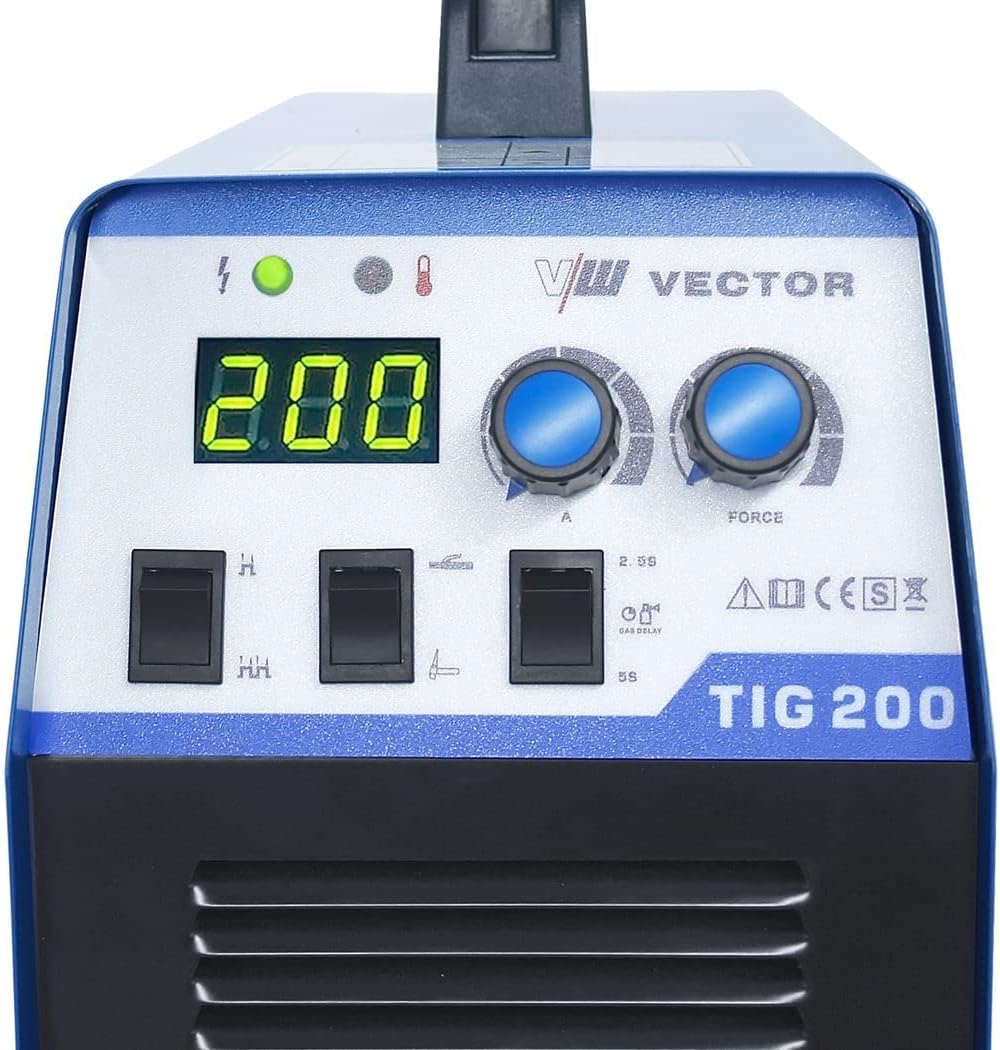
6.2. Mode Selection
Use the mode selection switch on the front panel to choose between TIG and MMA welding modes.
- TIG Mode: For Gas Tungsten Arc Welding. Requires inert gas.
- MMA Mode: For Manual Metal Arc (Stick) Welding.
6.3. Current Adjustment
Rotate the large knob on the front panel to adjust the welding current (Amperage). The digital display will show the selected current.
6.4. TIG Specific Settings
- HF Ignition: The machine uses High-Frequency ignition for TIG welding, eliminating the need for scratch starting.
- 2T/4T Control: Use the switch on the front panel to select between 2-stroke and 4-stroke torch control.
- 2T (2-Stroke): Press and hold the torch button to weld; release to stop.
- 4T (4-Stroke): Press and release the torch button to start welding; press and release again to stop. This mode is useful for longer welds to reduce hand fatigue.
- Gas Post-Flow: The machine automatically provides a gas post-flow to protect the weld puddle and tungsten electrode as it cools. The duration can typically be adjusted via a dedicated knob or switch (refer to Figure 4.2).
6.5. MMA Specific Settings
When in MMA mode, the following functions are active:
- Hotstart: Provides an initial boost of current to make arc striking easier.
- Anti-stick: Reduces the current if the electrode sticks to the workpiece, preventing overheating and making it easier to detach.
- Arc-Force: Automatically adjusts the current to maintain a stable arc, especially when the arc length changes.
7. Maintenance
Regular maintenance ensures the longevity and optimal performance of your welding machine.
- Cleaning: Periodically clean the exterior of the machine with a dry cloth. Use compressed air to blow out dust from the cooling vents. Ensure the machine is unplugged before cleaning.
- Cable Inspection: Regularly inspect all cables (power, TIG torch, ground, electrode holder) for cuts, fraying, or damaged insulation. Replace damaged cables immediately.
- TIG Torch Consumables: Check and replace TIG torch consumables (tungsten electrode, collet, collet body, ceramic nozzle) as they wear out.
- Gas Connections: Periodically check gas connections for leaks using a leak detection spray.
8. Troubleshooting
If you encounter issues, refer to the following common problems and solutions:
| Problem | Possible Cause | Solution |
|---|---|---|
| Machine does not power on | No power supply; Power switch off; Faulty power cable | Check power outlet; Turn on power switch; Inspect/replace power cable |
| No welding arc (TIG) | Ground clamp not connected; Incorrect TIG torch connection; Gas flow issue; Tungsten electrode not properly installed | Ensure ground clamp is secure; Check TIG torch connections; Verify gas supply and flow; Reinstall tungsten electrode |
| No welding arc (MMA) | Ground clamp not connected; Electrode holder not connected; Incorrect polarity; Wet electrodes | Ensure ground clamp is secure; Check electrode holder connection; Verify correct polarity; Use dry electrodes |
| Poor weld quality | Incorrect current setting; Improper gas shielding (TIG); Contaminated workpiece; Incorrect travel speed | Adjust current; Check gas flow and purity; Clean workpiece; Adjust welding technique |
| Overheating indicator on | Exceeded duty cycle; Blocked cooling vents | Allow machine to cool down; Clear any obstructions from vents |
If problems persist after attempting these solutions, please contact VECTOR WELDING customer support.
9. Specifications
Key technical specifications for the VECTOR WELDING DC TIG 200A IGBT Combi Welding Machine:
- Model Number: T2011
- Manufacturer: Vector Welding
- Material: Metal
- TIG Welding Current: 200 A
- MMA Welding Current: 170 A
- Ignition: High-Frequency (HF)
- Torch Control: 2-stroke / 4-stroke
- MMA Features: Hotstart, Anti-stick, Arc-Force
- ASIN: B0B7RPJFZC
- Date First Available: August 18, 2022
10. Warranty and Support
For information regarding warranty coverage, technical support, or spare parts availability, please refer to the documentation provided with your purchase or contact VECTOR WELDING directly through their official website or authorized distributors.